Download
1 / 18
210 likes | 498 Vues
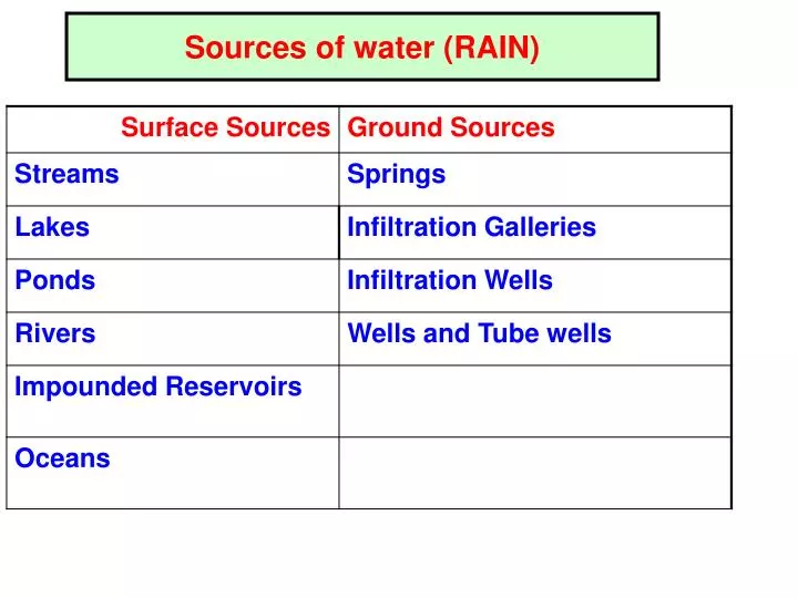
Sources of water (RAIN). Springs. Natural outflow of GW @ earth’s surface. Gravity springs : GW table rises high & water overflows though the sides of a natural valley or depression.

E N D
Springs • Natural outflow of GW @ earth’s surface. • Gravity springs : GW table rises high & water overflows though the sides of a natural valley or depression. • Surface springs : an impervious obstruction supporting underground storages becomes inclined causing water table to go up & get exposed to ground surface. • Artesian Springs : when water flowing through some confined aquifer is under pressure.
Wells • A water well is a hole usually vertical, excavated in the earth to bring GW to the surface. • Open Wells / Tube Wells.
Open Wells (Dug Wells) • Open masonry wells, 2 – 9 m dia, less than 20 m depth. Discharge 5 L/s • Walls built of brick or stone masonry or precast concrete ring • To improve yield of well, 10 cm dia hole @ centre of well is made (Shallow well/Deep Wells) • Shallow well rests in a pervious strata. • Deep well rests on an impervious ‘mota’ layer & draws its supply from the pervious formation lying below ‘mota’ layer. • A shallow well might be having more depth than a deep well
Infiltration Galleries (Horizontal Wells) • Horizontal tunnels (with holes on sides) constructed of masonry walls with roof slabs to tap GW flowing towards rivers/lake. • Constructed @ shallow depths (3-5m) along the banks of river either axially along or across GW flow. • Width (1m), depth (2m) , length (10 – 100m) • If large GW quantity exists, porous drain pipes are provided and they are surrounded by gravel and broken stone. • Yield, 15,000 L/day / Meter length • A collecting well @ shore end of gallery serves as sump from where water is pumped.
Infiltration Wells • They are shallow wells constructed under beds of rivers. • Deposits of sand exist at least 3m deep in river beds. As the water percolates down, impurities are removed. Quality of water is better than river water. • They are sunk in series in the bank of the river. • They are closed @ top & open & bottom. Manholes are provided @ top for inspection. • They are constructed of brick basonry with open joints. • Various infiltration wells are connected by porous pipes to sump called jack well.
Intakes • Structures used to withdraw water from various sources. • Lake / Reservoir / River /Canal/ Intake.
Lake Intakes • Submersible intake. • A pipe laid in the bed of the lake. • One end is in the middle of the lake & is fitted with bell – mouth opening covered with a mesh & protected by concrete crib. • Water enters in the pipe through bell-mouth opening & flows under gravity to the bank where it is collected in a sump – well & then pumped to TP.
River Intakes • A circular masonry tower (4-7m dia) constructed along bank of the river. • Water enters in the lower portion of the intake (i/e sump – well) from penstocks. • Penstocks are fitted with screens to prevent entry of floating solids. • No. of penstock openings are provided in intake to admit water @ different levels. • Opening & closing of penstock valves is done with wheels provided @ pump – house floor.
a) Wet Intakes • Constructed inside river @ suitable place. • A concrete circular shell filled with water upto water level inside the river. • Water enters through openings provided on outer circular shell, as well as on inside shell. • Water is taken to the bank of the river through the withdrawal conduit in the sump well from where it is pumped to WTP.
b)Dry Intake tower • In wet intake tower, water enters first in the outer shell then it enters in the inner shell. • In dry intake, water enters directly withdrawal conduit.
Reservoir Intake • An intake tower constructed on the slope of the dam. • Intake pipes are fixed @ different level to withdraw water at all variations of water level. • All inlet pipes are connected to one vertical pipe inside the intake well. • Screens are provided @ mouth of all intake pipes to prevent entry of floating matter. • Water entering the vertical pipes is taken to other side of the dam by means of an outlet pipe.
At the top of intake tower, sluice valves are provided to control flow of water. • Valve tower is connected to the top of the dam by means of foot-bridge gang- way. • For earthen dams, intake towers are separately constructed. • For RCC masonry dams, intake tower is constructed inside the dam it self.
Canal Intake • No need to provide multiple ports, as water level in canal remains constant. • A pipe placed in a brick masonry chamber constructed partly in the canal bank. • On one side of chamber, opening is provided with coarse screen for entrance of water. • A bell mouth fitted with a hemispherical fine screen is provided @ the mouth of the pipe. • Outlet pipe carries water to the other side of the canal bank from where it is taken to TP. • One sluice valve operated by a wheel from top of masonry chamber is provided to control flow of water in the pipe.