Download
1 / 16
160 likes | 315 Vues
Presentation #8: Rijndael Encryption. Team W1 Design Manager: Rebecca Miller 1. Bobby Colyer (W11) 2. Jeffrey Kuo (W12) 3. Myron Kwai (W13) 4. Shirlene Lim (W14). Stage VIII : March 24 th 2004 CHIP LEVEL LAYOUT. Overall Project Objective: Implement the new AES Rijndael algorithm on chip.

E N D
Presentation #8: Rijndael Encryption Team W1Design Manager: Rebecca Miller1. Bobby Colyer (W11)2. Jeffrey Kuo (W12)3. Myron Kwai (W13)4. Shirlene Lim (W14) Stage VIII: March 24th 2004 CHIP LEVEL LAYOUT Overall Project Objective: Implement the new AES Rijndael algorithm on chip 18-525 Integrated Circuit Design Project
Status • Design Proposal (Done) • Architecture Proposal (Done) • Size Estimates/Floorplan (Done) • Gate Level Design (Done) • Schematic Design (Fixed) • Input/Output Logic to SBOX Changed and Tested • Top Level Schematic Verified – Pipeline Works! • Layout • Component Layout (Done—Continually Changing) • Component Simulations • Chip Level Layout – Global Routing (80% Done) • To be Done • SPICE simulation of chip • Optimizations • Everything else… 18-525 Integrated Circuit Design Project
Status What needs to be done? • Global Routing • Everything is wired internally, needs to be globally connected • Slow and Fast Clock Routing • Select Line Routing • Vdd and Gnd Routing 18-525 Integrated Circuit Design Project
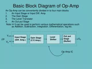
Top Level Schematic Input DFFs DFFs for Valid Out Add Round Key Clock Divider Select Logic Mux Tree In Mux Tree Out Final Text Out Final Text DFFs Round Permutations and Pipeline DFFs Key Expands and Pipeline DFFs Mux Tree In Mux Tree Out Select Logic
Verilog Re-Verification The Result of the Non-Resetting DFFs (Used to be junk values) @(posedge valid_in); key1[31:0] = 32'h00000000; text_in1[31:0] = 32'h91f0aca1; // Expected: c913f5ed vin = 1; @(posedge valid_in); key1[31:0] = 32'h851b64d9; text_in1[31:0] = 32'h00000000; // Expected: 30d0299b vin = 1; @(posedge valid_in); key1[31:0] = 32'hc0000000; text_in1[31:0] = 32'h00000000; // Expected: ec4b0b60 vin = 1; @(posedge valid_in); key1[31:0] = 32'hfff80000; text_in1[31:0] = 32'h00000000; // Expected: b3adb97e vin = 1; @(posedge valid_in); key1[31:0] = 32'h00000000; text_in1[31:0] = 32'h9b0cb284; // Expected: 69551ee1 vin = 1; #10000 $finish; end reg [4:0] counterx; always #5 clk = ~clk; initial begin counterx = 0; end always@(posedge clk) begin counterx = counterx + 1; if (counterx == 21) begin counterx = 0; end end initial begin clk = 1'b1; rst = 1'b1; #10 rst = 1'b0; #10 rst =1; @(posedge valid_in); text_in1[31:0] = 32'h00000000; // Expected: 1B3E9EDF key1[31:0] = 32'hFB473859; vin = 1; @(posedge valid_in); key1[31:0] = 32'b00000000000000000000000000000000; text_in1[31:0] = 32'h08f273e6; // Expected: 2DF5C18E vin = 1; @(posedge valid_in); key1[31:0] = 32'h00000000; text_in1[31:0] = 32'h10174E72; // Expected: 87FE42E7 vin = 1; @(posedge valid_in); key1[31:0] = 32'h00000000; text_in1[31:0] = 32'h30C42168; // Expected: 0BD9AFAC vin = 1; @(posedge valid_in); key1[31:0] = 32'h2F764A41; text_in1[31:0] = 32'h00000000; // Expected: 43B28B72 vin = 1; 18-525 Integrated Circuit Design Project
Updated Floorplan 350 um x 335 um Metal 4 Key DFFs and Input Logic 5th Round Key Expand SBOX and Control Logic Metal 3 Metal 2 Input to SBOX Logic & Select Output and Input Logic Metal 1 4 Rounds of Key Expand CLK Divider 4 Rounds of Round Permutation Input/Output Logic Select & Input Logic Text DFFs and Add RoundKey Final Text Out SBOX and Control Logic
LVSed – Outer Area – ROM and Input Logic and Output DFFs 11,992 Transistors
LVSed – Inner Area – AES Key Expand 12,296 Transistors
Final Dimensions • Total Area: 350 um x 335 um = 117250 sq. um • Transistor Count: 25,296 transistors • Transistor Density: 0.216 • Aspect Ratio: 1.045 • Estimated Clock Speed: 400MHz
Questions? 18-525 Integrated Circuit Design Project