Download
1 / 75
750 likes | 769 Vues
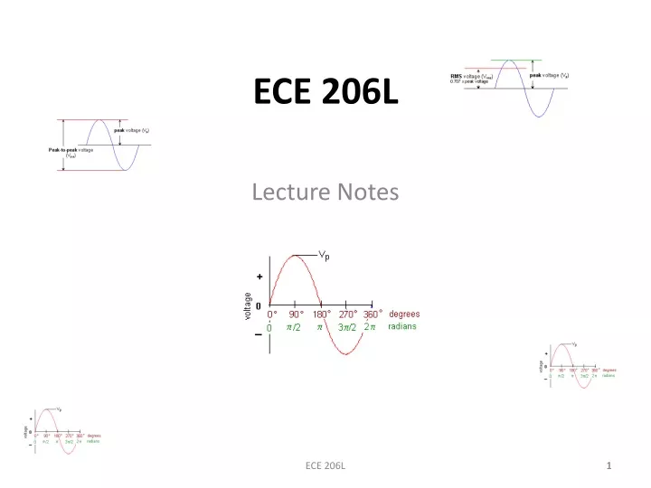
ECE 206L. Lecture Notes. 1. DC Current vs. AC Current. Direct current ( DC ) flows in one direction the circuit. Alternating current ( AC ) flows first in one direction then in the opposite direction. The same definitions apply to alternating voltage (AC voltage):

E N D
ECE 206L Lecture Notes ECE 206L 1
DC Current vs. AC Current • Direct current (DC) flows in one direction the circuit. • Alternating current (AC) flows first in one direction then in the opposite direction. • The same definitions apply to alternating voltage (AC voltage): • DC voltage has a fixed polarity. • AC voltage switches polarity back and forth. • There are numerous sources of DC and AC current and voltage. However: Sources of DC are commonly shown as a cell or battery, and for the AC current: Generators ECE 206L 2
The Sinusoidal AC Waveform • The most common AC waveform is a sine (or sinusoidal) waveform. • The vertical axis represents the amplitude of the AC current or voltage, in amperes or volts. • The horizontal axis represents the angular displacement of the waveform. The units can be degrees or radians. • The sine waveform is accurately represented by the sine function of plane trigonometry: y = rsinq where: y = the instantaneous amplitude r = the maximum amplitude q = the horizontal displacement ECE 206L 3
DefinitionPeak and Peak-to-Peak Voltage • Peak and peak-to-peak values are most often used when measuring the amplitude of ac waveforms directly from an oscilloscope display. • Peak voltage is the voltage measured from the baseline of an ac waveform to its maximum, or peak, level. Unit: Volts peak (Vp) Symbol: Vp • For a typical sinusoidal waveform, the positive peak voltage is equal to the negative peak voltage. Peak voltages are expressed without a + or - sign. • Peak-to-peak voltage is the voltage measured from the maximum positive level to the maximum negative level. Unit: Volts peak-to-peak (Vp-p) Symbol: Vp-p • For a typical sinusoidal waveform, the peak-to-peak voltage is equal to 2 times the peak voltage. Peak-to-peak voltages are expressed without a + or - sign . ECE 206L 4
Conversion • Convert Vp to Vp-p: Vp-p = 2 Vp • Convert Vp-p to Vp: Vp =0.5Vp-p • What is the peak-to-peak value of a sinusoidal waveform that has a peak value of 10 V? • What is the peak value of a sine wave that has a peak-to-peak value of 240 V? ECE 206L 5
Instantaneous Current and Voltage i = Ipsinθ Where: i = instantaneous current in amperes Ip= the maximum, or peak, current in amperes θ = the angular displacement in degrees or radians v = Vpsinθ Where: v = instantaneous voltage in volts Vp= the maximum, or peak, voltage in volts θ = the angular displacement in degrees or radians ECE 206L 6
Average Voltage • Average voltage is the average value of all the values for one half-cycle of the waveform. Unit: Volts average (Vave) Symbol: Vave • The average voltage of a sinusoidal waveform is equal to 0.637 times its peak value. • Vave = 0.637Vp • The average voltage is determined from just one half-cycle of the waveform because the average value of a full cycle is zero. Average voltages are expressed without a + or - sign ECE 206L 7
Average Voltage • Convert Vp to Vave: Vave = 0.637Vp • Convert Vave to Vp: Vp =1.57Vave • Determine the average value of a waveform that measured 16 Vp. Ans: 10.2 Vave • What is the peak value of a waveform that has an average value of 22.4 V? Ans: 35.1 Vp ECE 206L 8
Root-Mean-Square (RMS) Voltage • AC levels are assumed to be expressed as RMS values unless clearly specified otherwise. • RMS voltage is the amount of dc voltage that is required for producing the same amount of power as the ac waveform. Unit: Volts (V) Symbol: Vrms • The RMS voltage of a sinusoidal waveform is equal to 0.707 times its peak value. • Vrms = 0.707Vp • In a dc circuit, applying 2 V to a 1 W resistance produces 4 W of power. In an ac circuit, applying 2 Vrms to a 1 W resistance produces 4 W of power. RMS voltages are expressed without a + or - sign. ECE 206L 9
ConversionRoot-Mean-Square (RMS) Voltage • Convert Vp to Vrms: Vrms = 0.707Vp • Convert Vrms to Vp : Vp = 1.414Vrms • Determine the RMS value of a waveform that measures 15 Vp. Ans: 10.6 V • Determine the peak value of 120 V. . (Assume 120 V is in RMS) Ans: 170 Vp ECE 206L 10
Resistors in Series ECE 206L 11
Resistors in Parallel ECE 206L 12
Measuring Voltage Total Voltage: VR1+VR2 ECE 206L 13
Voltage Dividers The voltage is divided up in such that it is proportional to the resistances of the resistors in a series circuit. ECE 206L 14
Statistical Evaluation of Measurement Data and Errors • Average or mean value of a set of measurement • Deviation from the average value • Average value of the deviation • Standard deviation(from the concept of RMS) • Probability of error size in one observation
The Decibel (dB) The decibel, or dB, is a means of expressing the gain of an active device (such as an amplifier) or the loss in a passive device (such as an attenuator or length of cable). It is simply the ratio of output to input expressed in logarithmic form. The decibel was developed by the telephone company(Bel, to express the gain or loss in telephone transmission systems.
Calculating the Decibel (dB) • Now, imagine for a moment what it would be like to calculate the total gain of a string of amplifiers. It would be a cumbersome task at best, and especially so if there were portions of the cascade which were lossy and reduced the total gain, thereby requiring division as well as multiplication. • log (A x B) = log A + log B • log (A/B) = log A - log B • Using the Decibel: G = 10 log(Po/Pi) , Where: G = Gain in dB Po = Power output from the device Pi = Power input to the device Ex. : A length of coaxial transmission line is being fed with 150 watts from a transmitter, but the power measured at the output end of the line is only 112 watts. What is the line loss in dB? G = 10 log (112/150) G = 10 log 0.747 G = 10 (-0.127) G = -1.27 dB
Capacitors • Capacitors consist of two plates with a dielectric material in-between. When a potential difference is placed across the plates, a charge builds up until it is large enough to cause a discharge across the plates through the material. ECE 206L 18
Reading Capacitors Larger capacitors have the number of microfarads written on them directly. Smaller capacitors use a code based on the number of picofarads. We generally use microfarads, so… XYZ = XY * 10Z * 10-6mF ECE 206L 19
Capacitors in Series ECE 206L 20
Capacitors in Parallel ECE 206L 21
Impedance vs. Resistance • Resistance is a property of a material that causes a reduction in the rate of flow of electrons. • Impedance is the reduction in the rate of flow of electrons caused by the material (resistance) AND other the properties of the component involved (reactance). • Resistors have no reactance. So the impedance of a resistor is equal to its resistance only. • Reactance varies with the frequency of the input. Resistance remains the same at all frequencies. • Both impedance and resistance are measured in ohms.
ImpedanceDefinition A general measure of how a component or group of components pushes against the current flowing through it. • Impedance = resistance + reactance • Impedance is used to refer to the behavior of circuits with resistors, capacitors and other components. • When we consider components in a theoretical circuit diagram, the impedance of inductors and capacitors is their reactance only. Any resistance is modeled separately as a resistor. So theoretical capacitors and inductors have impedance, but no resistance.
Capacitor Impedance Real capacitors have effectively no resistance, so impedance is reactance for all capacitors. ECE 206L 24
What is Reactance • Reactance is the property of resisting or impeding the flow of ac current or ac voltage in inductors and capacitors. Note particularly we speak of alternating current only ac, which expression includes audio af and radio frequencies rf. NOT direct current dc. Inductive Reactance • When ac current flows through an inductance a back emf or voltage develops opposing any change in the initial current. This opposition or impedance to a change in current flow is measured in terms of inductive reactance. 2 * pi * f * L where: 2 * pi = 6.2832; f = frequency in hertz and L = inductance in Henries Capacitive Reactance • When ac voltage flows through a capacitance an opposing change in the initial voltage occurs, this opposition or impedance to a change in voltage is measured in terms of capacitive reactance. 1 / (2 * pi * f * C) where: 2 * pi = 6.2832; f = frequency in hertz and C = capacitance in Farads
Some examples of Reactance • What reactance does a 6.8 uH inductor present at 7 Mhz? Using the formula above we get: • 2 * pi * f * L • where: 2 * pi = 6.2832; f = 7 X 10+6 Hz and L = 6.8 X -6 Henries • Answer: = 299 ohms • What reactance does a 33 pF capacitor present at 7 Mhz? Using the formula above we get: • 1 / (2 * pi * f * C) • where: 2 * pi = 6.2832; f = 7 X 10+6 Hz and C = 33 X -12 Farads • Answer: = 689 ohms
Inductors An inductor is a coil of wire through which a current is passed. The current can be either AC or DC. ECE 206L 27
Inductors This generates a magnetic field, which induces a voltage proportional to the rate of change of the current. ECE 206L 28
Combining Inductors Inductances add like resistances Series Parallel ECE 206L 29
Inductor Impedance Real inductors always have a small resistance (that is not shown in these circuits). The impedance of the theoretical inductor shown is only its reactance. ECE 206L 30
ImpedanceDefinition A general measure of how a component or group of components pushes against the current flowing through it. • Impedance = resistance + reactance • Impedance is used to refer to the behavior of circuits with resistors, capacitors and other components. • When we consider components in a theoretical circuit diagram, the impedance of inductors and capacitors is their reactance only. Any resistance is modeled separately as a resistor. So theoretical capacitors and inductors have impedance, but no resistance.
Equipment Impedances • Each measuring device changes the circuit when you use it. • The impedance of the device helps you understand how much. • Device Impedances • Function Generator: 50 ohms • Scope: 1Meg ohms • DMM (DC voltage): 10Meg ohms • DMM (AC voltage): 1Meg ohms • DMM (DC current): 5 ohms (negligible) ECE 206L 33
Effect of Impedance on Circuit Function generator thinks it is putting out the same thing. Output is clearly different. ECE 206L 34
Effect of Impedance on Circuit The function generator has an output impedance of much less than 50Ω, so we can ignore it. ECE 206L 35
Kirchoff’s Laws sum of currents entering a junction is the same as the sum of the currents leaving a junction sum of voltages in any loop is zero
Oscilloscope Tutorial • The oscilloscope is basically a graph-displaying device • It draws a graph of an electrical signal. • In most applications the graph shows how signals change over time: • the vertical (Y) axis represents voltage • the horizontal (X) axis represents time.
Oscilloscopes Horizontal sweeps at a constant rate. Vertical plates are attached to an external voltage, the signal you attach to the scope.
Cathode Ray Tubes Variation in potential difference (voltage) placed on plates causes electron beam to bend different amounts. “Sweep” refers to refreshing repeatedly at a fixed rate.
Scope (Con’t) • This simple graph can tell you many things about a signal: • You can determine the time and voltage values of a signal. • You can calculate the frequency of an oscillating signal. • You can see the "moving parts" of a circuit represented by the signal. • You can tell if a malfunctioning component is distorting the signal. • You can find out how much of a signal is direct current (DC) or alternating current (AC). • You can tell how much of the signal is noise and whether the noise is changing with time.
If a signal repeats, it has a frequency. The frequency is measured in Hertz (Hz) and equals the number of times the signal repeats itself in one second