Download
1 / 31
350 likes | 590 Vues
PMU simulation and application for power system stability monitoring. Harmeet Kang Areva Technology Centre – Stafford, UK. Sept. 2009 MOSCOW. Historical Perspective. Impossible to compare data from geographically different locations No context to the measurements Slow RTU data

E N D
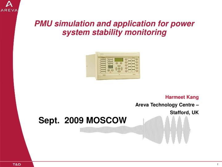
PMU simulation and application for power system stability monitoring Harmeet Kang Areva Technology Centre – Stafford, UK Sept. 2009 MOSCOW
Historical Perspective • Impossible to compare data from geographically different locations • No context to the measurements • Slow RTU data • Technology cost prohibitive
q peak Xi (n) q Xr (n) 1pps What is a Phasor IEEE C37.118 specifies that the angle is 0 degrees when the maximum of the signal to be measured coincides with the GPS pulse and -90 degrees if the positive zero crossing coincides with the GPS pulse.
Anti Aliasing PMU device basics GPS Receiver Oscillator Microprocessors A / D Digital Digitised IEEE C 37 . 118 Data Analog Samples Electrical Data Frame over signal Serial or Ethernet P 847 PMU ( TCP / UDP )
Anti Aliasing PMU device basics Small error GPS Receiver Oscillator Fixed delay in gathering data CT/VT Mag/Angle Errors Small error Microprocessors A / D Digital Digitised IEEE C 37 . 118 Data Analog Samples Phase delays /Variable Electrical Data Frame over signal Serial or Ethernet P 847 PMU ( TCP / UDP )
GPS input 200ms • Output Site 1 +/- 1ms Light ON Leading edge is timing point Light OFF Time • Output Site 2 <100 ns Light ON Light OFF Time
Acceptable Total Vector Error (TVE) 1% TVE ~ 0.5 degrees ~ 26 msec @60Hz Where Xr (n) and Xi (n) are the measured real and imaginary components and Xr and Xi are the reference values. This measurement accuracy varies with the magnitude and frequency of the input signal.
Measurement Window Filter Coefficients are chosen to provide A zero degrees phase shift if the middle of the window corresponds to the peak of the signal
Filter Length • Programmable • 1 – 7 Cycles • Default - 5 Cycles
Impact of Filter Length Particularly important to have good noise rejection as inter area and local oscillations are around 0.1 -3 Hz
PMU’s in a System • PMU1 • PMU2 • PMU3 • PMU4 • E-terra • PDC
IEEE C37.118 Protocol • Configuration =>To PDC • Header =>To PDC • Data => To PDC • Command <= From PDC
PMU Locations and Number of • Which feeders are key to the interconnection between grid regions • Which nodes exhibit large shifts in power angle based on a loss of generation, load and change in topology. • Which areas are of interest from a load modelling perspective • Which areas of the grid are known to contain dynamic stability issues • Which areas can form frequency Islands • Which areas of the grid are prone to voltage collapse • Which nodes will be most beneficial for the current state estimator improvement and a future linear state estimator
PMU Locations and Number of Phenomena Power Angle Load Dynamics Stability monitoring Frequency Islands Voltage Collapse State Estimation
Small Signal Stability Ability of a power system to maintain synchronism When subjected to small disturbances. In today’s practical power systems, the small signal Stability problem is usually of insufficient damping of system oscillations Ref: Power System Stability and Control Prabha Kundur
System Oscillations Ref: UNDERSTANDING POWER SYSTEM STABILITY Michael J. Basler and Richard C. Schaefer
Modal Analysis Oscillatory Modes and associated damping factors for two buses in a system after a small disturbance
Effect of Data Transmission rate of application Every PMU measurement Every second PMU measurement Every tenth PMU measurement Every second