Download
1 / 51
510 likes | 667 Vues
The Link Layer: Framing, Addressing, and Forwarding. GZ01 Networked Systems Kyle Jamieson Lecture 4 Department of Computer Science University College London. The link layer. The link layer (L2) has the job of transferring a datagram point-to-point over a link.

E N D
The Link Layer: Framing, Addressing, and Forwarding GZ01 Networked Systems Kyle Jamieson Lecture 4 Department of Computer Science University College London
The link layer The link layer (L2) has the job of transferring a datagram point-to-point over a link Unit of data is called a frame at the link layer
The link layer: Context • Datagram transferred by different link protocols over different links on its path • Each link protocol provides different services • Reliability • Error correction • Half/full duplex
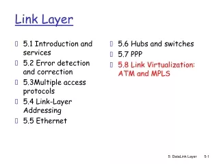
Today • L2 addressing and interaction with L3 • Link layer switching • Learning switches • VLANs • Spanning Tree Protocol • The Point-to-Point Protocol (PPP) • Link virtualization: MPLS
Comparing addressing schemes • Network layer address (IP address) • Function: move datagram to destination network • 32-bit address, dotted quad notation a.b.c.d where each component is an eight-bit unsigned integer • Hierarchical address space • Link layer address (MAC address, Ethernet address): • Function: move frame from one point to another point on the same network • 48-bit address (in most LANs) • Burned in NIC ROM, also sometimes software settable • Usually a flat address space
Link-layer addressing • Each adapter on LAN has unique link layer address, my_station_id • Special broadcast address broadcast_id • Each L3 protocol registers itself in net_handler array • L2 address-related functionality for inbound frames: • Test received_frame.destination against my_station_id or broadcast_id, drop if neither match • handler net_handler • [received_frame.net_protocol] • call handler(received_frame.payload)
Link layer addresses aren’t routable • Network layer routes from one network to another (link layer address)
Mapping network to link addresses • Goal: Translate from nework_send(data, length, IP, N) to link_send(data, length, IP, enet/18) • Name-mapping table: example of soft state
The Address Resolution Protocol (ARP) L sending a datagram to N: L: network_send(data, length, IP, N) L: link_send(“where is N?”, length, ARP, broadcast_id) N: link_send(“N is at enet/18”, length, ARP, enet/17) L: link_send(data, length, IP, enet/18) ARP table at L: Internet Address enet/ station TTL N 18 20 min
ARP’s role in L3 routing • Walkthrough: send IP data from L to E via router K • Router K • Two ARP tables: one for each subnet • Two interfaces (interface ids 6, 4): one for each subnet, with two link-layer addresses (19, 27)
Example: routing between subnets L sending a datagram to E: L: network_send(data, length, IP, E) L: link_send(data, length, IP, enet/28) L: ARPs for K’s link layer address (enet/19) L: link_send(data, length, IP, enet/19) K: ARPs for E’s link layer address (enet/28) on link/4 K: link_send(link/4, data, length, IP, enet/28)
Hubs • Replicating device: bits coming in go out all ports • Operates at the physical layer (L1) • Doesn’t run CSMA/CD: immediately replicates bits • Collisions possible between all hosts • No frame buffering at the hub • Physical limitations: can’t grow collision domain too big Hub
Ethernet nowadays: Switched A • Hosts have dedicated, direct connection to switch • Switches buffer frames • Ethernet protocol used on each incoming link, but no collisions • Each link in own collision domain • Switching: A → A’ and B → B’ simultaneously, without collisions F B 1 2 6 3 4 5 Switch S C E D
The switch table • How to tell which port to forward packet? • The switch table: LAN addr Port TTL • Switch table initially empty • Example of “soft state” • How to build up switch table entries? A F B 21 22 26 1 2 6 3 Switch S 4 5 23 25 24 C E D
Building the switch table: Self-learning • Switch table: (LAN addr, port id, TTL) • Receive a packet from LAN addr enet/src to LAN addr enet/dst: • Add enet/src to switch table with incident port id • If enet/dst is broadcast_id: forward out all ports except id • If enet/dst in switch table, lookup entry and forward to resulting port id • Otherwise, forward out all ports except id • Periodically flush link table entries based on TTL
Building up the switch table: example • A S: [A (enet/21) D (enet/24)] S (all ports) • B S: [B (enet/22) C (enet/23)] S (all ports) • D S: [D (enet/24) B (enet/22)] S port 2 only Switch table: LAN addr Port TTL enet/21 1 20 min enet/22 2 20 min enet/24 4 20 min A F B 21 22 26 1 2 6 3 Switch S 4 5 23 25 24 C E D
Hubs versus switches Hub Switch Link-layer (L2) device Selectively forward frame to one or more outgoing links CSMA/CD MAC Buffers frames Hosts are unaware of presence of switches No configuration needed • Physical layer (L1) device • Replicating device: bits in go out all ports • No medium access control • No frame buffering • Hosts are unaware of presence of hubs • No configuration needed
Interconnecting LANs • Switches can connect LANs as well as hosts • Sometimes called bridges in this context S4 Link layer addresses 1 3 S1 2 S3 1 1 11 1 S2 2 21 2 4 3 A 4 3 12 13 22 D 23 B C F E
Interconnecting LANs: example Suppose C sends frame to F, F responds to C S4 Link layer addresses 1 3 S1 2 S3 1 1 11 1 S2 2 21 2 4 3 A 4 3 12 13 22 D 23 B C F E What traffic gets sent, and which additions to switch tables? S1: enet/13: port 4, enet/23: port 1 S4: enet/13: port 1, enet/23: port 2 S2: enet/13: port 1, enet/23: port 4 S3: enet/13: port 1
Interconnecting switches: loops • S1, S4, S2 form loop, packets forwarded around forever! • Why do loops form? • Inadvertently: many people responsible for network, one person adds a bridge • Intentionally: more connections adds redundancy for failure • Consequence: Can’t learn the direction of a source if it’s in more than one direction, so bridge learning algorithm breaks S4 Link layer addresses 1 3 S1 2 S3 1 1 11 1 S2 2 5 2 4 3 A 4 3 12 13 22 23 B C F E
The spanning tree protocol (STP) • Manager at DEC asked Radia Perlman to build a switch (bridge)to connect two Ethernets • Perlman’s idea: Switches agree on a spanning tree • Subset of the topology that is connected • Loop-free • Some path between every pair of LANs • Implementers at DEC resisted (wanted simplest possible design), first customer site connected bridge to one Ethernet twice, generating a broadcast storm • Mechanism: • Switches block some ports from sending or receiving data • Switches continue using the learning switch algorithm to forward over the spanning tree
Spanning tree protocol (STP): Outline • Elect one root switch (switch with the lowest ID) • Compute shortest paths tree from root to each switch S • Note which port of S is on path to root: root port (R) • All switches connected to a LAN choose a designated switch to forward frames to root (switch on path to root from LAN) • e.g. switch 2 is designated for the LAN below • i.e., each port decides if it is a designated port (D) • Block all other ports: blocked port (B) Port number LAN 1(R) 1(D) 2 3 Switch ID Switch
STP: Messages and switch state • All switches exchange configuration messages switch X sends: (Root identifier, distance to root, X) • Configuration messages are never blocked • Switch X generates configuration messages periodically with a “clock tick” timer, initially sending (X, 0, X) • State at each switchX: • Root identifier (initially X) • Configuration message to send (initially (X, 0, X)) • State at each port: • Forwarding data traffic or blocking data traffic (initially forwarding) • “Best” configuration message + age of that message (initially empty)
Electing a per-LAN designated switch • Designated port rule: At a switch, for each port p • Consider all configuration messages received on port p and the configuration message the switch would send • If receive “better” configuration message on a port p, don’t send configuration messages on port p, otherwise p is designated, send on p • Rule for comparing configuration messages: (R1, d1, X1) better than (R2, d2, X2) if R1 < R2or (R1 = R2and d1 < d2) or (R1 = R2and d1 = d2and X1 < X2) • E.g.: 2 sends (2, 0, 2); 3 sends (3, 0, 3); (2, 0, 2) better than (3, 0, 3) • Switch 2, port 1 sends configuration message • Switch 3, port 1 does not send configuration messages 1(D) 1 2 3
STP: initial startup phase 1(D) • Initially, X generates configuration messages periodically, sending (X, 0, X) • All ports designated and forwarding • Result: For each LAN, one attached switch (the designated switch) transmits configuration messages 87 2 78 1(D) 5 1 4 2(D) 90 3 1(D) 2 2 3(D) 66 5 1 2 101 2 1 2 2(D) 1(D)
Calculating root ID and cost to root • Switches continuously take the following steps: • Root ID rule: Root ID r at switch X is the minimum of X and root IDs received at all ports • Calculating distance to root d at switch X: • If X is the root (X = r), d = 0 • Otherwise, X is not the root (X ≠ r): • d = one plus the minimum cost from configuration messages received on all ports (transmitter field breaks ties). Suppose this comes from port p. • Root port rule: Designate port p as a root port • Switch X’s configuration message is now (r, d, X). Reapply designated port rule on all ports • Blocked port rule: Don’t forward data to or from a port if it is not a designated port or a root port
STP: calculating root ID (2,2,78) 1(D) (2,2,87) 87 (2,1,90) 5(D) 2(B) 78 1(R) 1(B) 4(D) (2,1,90) 2(R) 90 (2,1,66) 1(D) 3(B) 2(R) 2(R) 66 5 1(R) 3(D) (2,1,5) 2(B) (2,2,101) (2,0,2) 2(D) 101 1(D) (2,0,2) 2 2(B) 1(R) 90’s root ID r: 2, d = 1 90’s message: (2, 1, 90) 5’s root ID r: 2, d = 1 (port breaks tie) 5’s message: (2, 1, 5)
STP: Handling topology changes • Configuration messages also contain age: (r, d, X, age) • age = 0 when sending configuration message • Best configuration message for each port contains age • Age incremented each unit of time • If age reaches some threshold (max age), discard that configuration message and recalculate using all rules • Recalculate when: • Receive better or newer configuration message on port p: overwrite existing configuration message • Timer ticks: increment message age in stored messages for each port
STP: Handling failures (2,2,78) 1(D) 87 (2,1,90) 5(D) 2(B) 78 1(R) 1(D) (2,1,90) 4(D) (2,1,90) 2(R) 90 3(B) 2(R) 2(R) 66 5 1(R) 3(D) (2,1,5) 2(B) (2,0,2) 2(D) 101 1(D) (2,0,2) 2 2(B) 1(R) 90’s root ID r: 2, d = 1 90’s message: (2, 1, 90)
STP: Handling new bridges (2,2,78) 1(D) • Don’t want loops, even for short periods of time • Switches 2, 5, 101 send messages immediately, with current age in table • On power-up, switch puts its ports in new pre-forwarding state: sends configuration messages as if designated, but doesn’t forward data 87 (2,1,90) 5(D) 2(B) 78 RP 1(D) (2,1,90) 4(D) (2,1,90) 2(R) 90 3(B) 2(R) 2(R) 66 5 1(R) 3(D) (2,1,5) 2(B) (2,0,2) 2(D) 101 1(D) (2,0,2) 2 2(B) 1(R) (95,0,95) 2(D) (95,0,95) 1(D) 95
Virtual LANs (VLANs) Switched LANs are great, but: • Lack of traffic isolation between LANs • Security, privacy concerns • Inefficient use of switches • One switch per administrative group • Moving users requires physical rewiring VLAN idea: run multiple virtual LANs over a single LAN
Virtual LANs (VLANs) 1 9 15 2 4 8 10 16 … … Computer Science Department Electrical Engineering Department • Traffic isolation: colors = broadcast domains • Easily reconfigurable port assignments • Routing between VLANs: layer 3 routing functionality
The split between L2 and L3 • L2 is point-to-point, L3 has source and destination • Then Ethernet came, world got confused and thought Ethernet was a competitor to L3 • Perlman: “Should have been called ‘Etherlink.’” • Why can’t Ethernet replace IP? • Flat addresses • No hop count (loops would be a disaster) • No fragmentation, reassembly
In each and every host Network adapter Physical card Chip in a device Attaches to host’s system bus Implemented both in hardware and software Software: device driver running on CPU Hardware: FPGA, ASIC in network adapter Where is the link layer implemented? Host Application Memory CPU Transport Network Link Network adapter Controller Link PHY Physical
Hardware or software? Host • Software is more flexible, unless you need: • Time-critical functionality • Backoff transmission timing in Ethernet • Highly parallel processing • Dot product computations for CDMA, filtering for the PHY Application Memory CPU Transport Network Link Network adapter Controller Link PHY Physical
Today • L2 addressing and interaction with L3 • Link layer switching • Learning switches • VLANs • Spanning Tree Protocol • The Point-to-Point Protocol (PPP) • Link virtualization: MPLS
Point to Point link layer • One sender, one receiver, one link: easier than broadcast link: • No Medium Access Control • No need for explicit link layer addressing • e.g., dialup link, ISDN line • Popular point-to-point link layer protocols: • PPP (point-to-point protocol) • HDLC: High level data link control • Data link used to be considered “high layer” in the stack!
PPP Design Requirements [RFC 1557] • Packet framing: encapsulation of network-layer datagram in data link frame • Carry network layer data of any network layer protocol (not just IP) at same time • Ability to demultiplex upwards • Bit transparency: must carry any bit pattern in data • Error detection (but no error correction requirements) • Connection liveness: detect and signal a link failure to the network layer • Network layer address negotiation: endpoints can learn and configure the other’s network address
PPP non-requirements • No error correction nor error recovery • No flow control • No in-order data delivery requirement • No need to support multipoint links (e.g., polling) Error recovery, flow control, data re-ordering all relegated to higher layers!
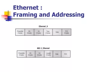
Framing frames: the problem • We have seen how to frame bits • Ethernet: Manchester encoding, synchronization on edges • Result in general: infinite stream of bits • Problem: where does each frame begin and end?
Frame separators • Choose some pattern of bits as a frame separator e.g.: 1111111 Bit stuffing algorithm Modify the outgoing data stream as follows: • At sender: 111111 → 1111110 • At receiver: 1111110 → 111111 1111111 → (end of frame) Seven 1’s Six 1’s Six 1’s Seven 1’s
PPP: Byte Stuffing • At the sender: • Stuff control escape byte <01111101> before each flag byte occurring in the data • Stuff control escape byte before each control escape byte occurring in the data • At the receiver: • Escape, flag byte discard escape byte, keep flag byte, continue data reception • Single flag byte: interpret as the flag byte • Two escape bytes discard one
PPP Byte Stuffing: Example Data in: 01111101 (escape) b4 01111110 (flag) b2 b1 Data out: b1 b2 01111110 (flag) b4 01111101 (escape) PPP Sender PPP Receiver 01111101 01111101 b4 01111110 011111101 b2 b1 stuffed escape stuffed escape
Today • L2 addressing and interaction with L3 • Link layer switching • Learning switches • VLANs • Spanning Tree Protocol • The Point-to-Point Protocol (PPP) • Link virtualization: MPLS
Internetwork layer (IP): • Addressing: internetwork appears as single, uniform entity, despite underlying local network heterogeneity • Network of networks The Internet: virtualizing networks Gateway: • Embed IP packets in local packet format, or extract them • Route (at internetwork level) to next gateway, or end host gateway ARPAnet ALOHAnet
Cerf & Kahn’s Internetwork architecture What is virtualized? • Two layers of addressing: IP and local network • IP makes everything homogeneous • Underlying local network technology • Cable TV links • Satellite links • Telephone modem links • Ethernet, WiFi • MPLS networks • “Invisible” at IP layer: all like a link to IP
Multiprotocol label switching (MPLS) • A large network, viewed as a link, i.e., a type of link layer • Initial goal: Speed up IP forwarding by using fixed length label (instead of IP address) to do forwarding • Borrowing ideas from Virtual Circuit (VC) approach • But: IP datagram still keeps IP address • Insert MPLS header between L2 and L3 headers: PPP or Ethernet header IP header remainder of link-layer frame MPLS header label Exp TTL S 5 1 3 20
MPLS-capable routers • Label-switched routers • Forward packets to outgoing interface based only on label value (don’t inspect IP address) • MPLS forwarding table ≠ IP forwarding table • Signaling protocol needed to set up forwarding • Forwarding possible along paths that IP alone would not allow (e.g., source-specific routing) • Use MPLS for traffic engineering • Must co-exist with IP-only routers
in out out label label dest interface 10 6 A 1 12 9 D 0 in out out label label dest interface in out out label label dest interface 8 6 A 0 6 − A 0 Example: MPLS forwarding tables in out out label label dest interface − 10 A 0 − 12 D 0 − 8 A 1 R6 0 0 D 1 1 MPLS-enabled router R3 R4 R5 0 0 A R2 R1 Standard IP router
Summary: Link layer functionality • Addressing hosts on shared links • The ARP protocol • Error detection and correction (Lecture 2) • Flow control • Framing bits and packets • Reliable delivery point-to-point delivery (next time) • Sharing: Medium access control (Lecture 3)