Download
1 / 19
190 likes | 378 Vues
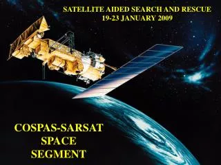
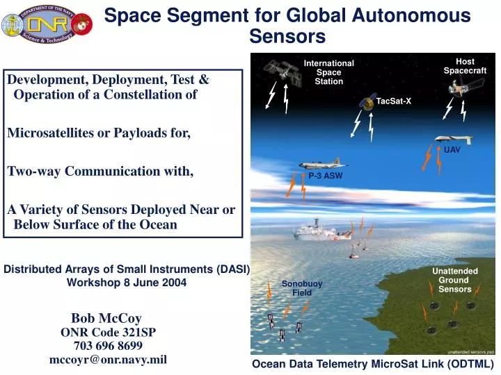
Space Segment for Global Autonomous Sensors. Host Spacecraft. International Space Station. Development, Deployment, Test & Operation of a Constellation of Microsatellites or Payloads for, Two-way Communication with, A Variety of Sensors Deployed Near or Below Surface of the Ocean.

E N D
Space Segment for Global Autonomous Sensors Host Spacecraft International Space Station Development, Deployment, Test & Operation of a Constellation of Microsatellites or Payloads for, Two-way Communication with, A Variety of Sensors Deployed Near or Below Surface of the Ocean TacSat-X UAV P-3 ASW Distributed Arrays of Small Instruments (DASI) Workshop 8 June 2004 Unattended Ground Sensors Sonobuoy Field Bob McCoy ONR Code 321SP 703 696 8699 mccoyr@onr.navy.mil Ocean Data Telemetry MicroSat Link (ODTML)
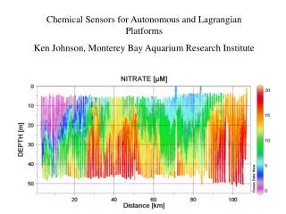
Argo Profiling Floats • Operational Characteristics • Surface to 2,000 m • Salinity, Temperature and Pressure • Argos DCS Constraints: • Repeat Transmission every 60 to 72 seconds, 10-12 hours every 10 days • Normally around 50 pressure levels (range 33 to 115) • Data 348 to 464 bytes (12 to 16 Argos messages) • $1.2 M “value-added” processing • Future Requirements • On Demand transmission 500 pressure levels (4 Kb) within one hour with reduced power demands for communications • Two-way communications (not necessarily on demand) for programming • $100-150K Target data telemetry cost
Data Assimilation for Meteorological Forecast Over 3000 aircraft provide reports of pressure, winds and temperature during flight.
Iridium, GlobalStar & ORBCOMM • Existing ground-to-space/ground networking (Orbcomm, Iridium) were developed for voice and data, and rely heavily on fixed infrastructure, and power-intensive transmissions at VHF frequencies • ORBCOMM/Iridium are good for large littoral buoys where transmit power is not an issue and where L-Band attenuation (wave shadowing or microorganism growth) is not an issue • Current market (~20M/yr) is sufficient to sustain current systems but is insufficient to replenish the satellite constellation • Industry focus is not on low data-rate (<10,000 b/s) customers • Existing systems are not IP-like and require extensive groundstations and satellite monitoring • Operational Expense & Operations over the ocean
Global Data Communications “On the Move” Small, Mobile and Disadvantaged Platform Transceiver Terminals (PTTs) Laptop Computers/Transceivers Availability Robust RF Links – In Water and Under Cover Capacity Many Users in the Field Service Simultaneous Data Nets Assured Access Acknowledgement That Messages Got Through Interoperability Seamless Connectivity to Other Systems Ocean Data TelemetryMicroSat Communications Relay System A Global Communications System ProvidingNear Real-Time Situational Awareness Is Essentialfor the Next Generation Ocean Observing System
Microsatellite Constellation Goals • Demonstrate 2-Way communication with small disadvantaged sensors anywhere in the world • UHF transmission compatible with Service ARGOS, But with the following enhancements: • Significantly higher bandwidth (4800 b/s vs <256 b/s) • 2-Way delay-tolerant communication • “IP-like” message packaging • New protocol for increased battery life & Non-GPS geolocation • Method to provide acknowledgement that command sequences were received (ACK/NACK) • Increased signal-to-noise at the host satellite via coding, a bi-directional software radio, similar to e-mail to forward messages to user/sensor with defined addressing schemes • Enhanced computer speed & storage for on-board data processing • System architecture allows evolution and expansion for future sensors • System capable of being deployed as a mix secondary payloads aboard host space vehicles (e.g. International Space Station, DMSP, TACSAT) or low-cost micro-satellites e.g., STP (Navy PG or USNA).
Multiple Access With Collision Avoidanceby Invitation (MACA-BI) Network Protocol
Spacecraft (S/C) Avionics Measure Doppler Shift on Uplink Carrier Frequency As S/C Approaches and Moves Away From Location of PTT At Point of Inflection of Doppler Curve (i.e., Rx vs. Tx Frequencies Are Equal), PTT Position Is Perpendicular to S/C Ground Track Slope of Curve at Inflection Point Determines Distance From PTT to S/C Ground Track Location Errors of ~125m to 3000m (i.e, PTT Local Oscillator Stability, Number of Samples, and S/C Ephemeris Errors) Location Errors Are Greatest When PTT Is ~170 km of the S/C Ground Track or More Than 2,700 km From S/C Ground Track Other Factors: PTT Oscillator Stability – Mean PTT Short Term Frequency Stability <4x10E-5 (20 Minutes) Mean PTT Frequency Must Not Vary > 24 Hz Between Multiple Passes (Two Overpasses) PTT Altitude Creates Errors Due to Changes in Assumed Altitude (Sea Level) Coupled in the “Across-Track” Coordinate of the Fix With Little Effect on the “Along-Track” Coordinates GeoLocation Determination via Doppler Shift Doppler Shift Metrology Sources of Location Spacecraft Requirements • Location Determination Requires Ephemeris Within 300m (“Along-Track”) and 250m (“Across-Track”) • Location Determination Requires >5 Doppler Measurements w/ >420 sec Interval Between First and Last Measurements w/ 240 sec Separation (Minimum Accuracy)
DC-DC Converters 3.3V, 5V, ±12V 1553 Interface 24VDC Input Configurator Discrete I/O Motor Drive Interfaces (0 Populated) Actel 54SXnn FPGA MCU RS232 Linear Regulators 2.5V, ±5V Analog Local SRAM Shared SRAM EEPROM Expansion Interface (0 Populated) LVDS Interface PROM XILINX Virtex400 FPGA Expansion Interfaces 0 Populated) Expansion Interface (0 Populated) Expansion Interface RS422 Interface RS232 Interface Communications RelayPayload Breadboard
ODTML MicroSat Configuration Communications Relay Processor • Payload Minimum Resources Available: • ~25 Watts Orbital Average Power (OAP) - Basic • ~5 kg Mass (Basic) • 0.3m x 0.75m x 0.8m Size • 350 b/s Average Payload Stored Data + 100 b/s Payload Housekeeping Stored Data Communications Relay Transceiver Spacecraft Avionics (Includes 3 Micro Gyros) ODTML Payload Provides Uplink/Downlink Communications Three Axis Magnetometer Magnetic Torque Rods Heritage LightBand Separation Lithium Ion Battery Hydrazine Propulsion System Thermally Stable With Constant Dark and Sun Sides Spacecraft Structure • Body Mounted GaAs Solar Arrays: • Allows Common Satellite Design for All Orbit Planes • Minimizes Body Drag Perturbations on Gravity Gradient (G-G) Stabilizing Torques • Improves Reliability • Reduces Cost and Simplifies Integration Simple Design and Interfaces Enable Ease of Development and Integration
UHF Eggbeater Antenna Omni-Directional Circular Polarization (RHCP) Communications Relay Payload Repackaged for Ground Environment Plus High Power Amplifier (HPA) Laptop Interface (Portable Ops) OR PC-Based Mail Server and Remote Intelligent Monitoring System (RIMS) for Fixed Gateway Low Cost Communications GatewayUses Same Electronics Suite As Buoy System Characteristics
EELV SpaceEx Falcon Potential Launch Opportunities Low-cost launch opportunities: • Alternate Launch Vehicles • EELV Secondary Launch • 4 tons excess for each DMSP launch • SpaceEx Falcon - TacSat follow-on • University MicroSat Designs • CubeSat • ASTRID/MUNIN • USNA PC Sat CubeSat Cubesat PC Sat MUNIN ChipSat
TacSat-1 Program ElementsNavy Highlights $12M • MICROSATELLITE: • 1 yr Life, 110kg, 186W • 40in dia. x 20in high • 500km, 64º inc. • LAUNCH VEHICLE: Falcon by SpaceX • New, Privately Developed • LOX-RP1 gives ~1000 lb to 500km • 60klb, 70ft by 5.5ft dia. • Navy Contract • GROUND STATION: Blossom Point MD • Navy Facility • With VMOC (Virtual Mission Operations Center) for SIPRNET Tasking & Data Dissemination • PAYLOADS: • CopperField-2S: Navy TENCAP • SEI: NRL/ONR? Developed • Visible & IR Cameras (Army NVL) $3M • AIRCRAFT: • EP-3’s: 1 Fixed & 3 Mobile RORO Units; Also RJ’s (TBD #) Expected • Implementing an Naval, ONR Cross-Mission CONOP
TacSat-1 Spacecraft Components • IR Camera & UHF Radio • SEI Hermetically Sealed Chassis (CuF-2S is Similar) • Rubidium Clock & Low Cost Receivers (0.5-18GHz Range Used) • Specific Emitter Identification (UYX-4) & Copperfield-2S Payload Hardware • Spacecraft Bus & EAGE Hardware UYX-4 IR Camera Does NOT Require Cryo-Cooling CURRENT Technology by COMPUTER INDUSTRY STANDARDS (3 Million Gate FPGA) Fans 2 Places Receivers Clock
Program Plan • Build satellite/aircraft payload and test via aircraft flight(s) (2005) • Orbital test using existing orbital UHF satellite (2005) • (10kg NanoSat; half duplex mode – SpaceQuest) • Deliver satellite payload on International Space Station (2006) • 57º Inclination (via Space Test Program) • Launch polar payload/satellite (2007) on TacSat-n, DMSP or STP payload of opportunity • Test ocean to space system with realistic RF & ocean environment • Communication links with actual Doppler • Distance fading • Actual environment (shadow fading - wave height) • Operate autonomously, unattended
Tac-Sat n Near Term 2 Planes 6-8 Hrs Revisit time International Space Station Sp Ultimate goal 6 Satellites in 3 Planes 2.5 Hr revisit
ONR Small Business Innovation Research (SBIR) Topic N02-062 (ODTML) • DOD Space Exp Review Board (SERB) ONR-0301 (Ranked Experiment) Ocean Data Telemetry MicroSat Link (ODTML) Concept of Operation Operational Capability • Communications Relay Payload to Support an Integrated Global Ocean Observing System via MicroSat or Host Platform • Data Infiltration and Exfiltration for Small, Mobile, and Low-Power Ocean Buoys and Sensor Transceiver Nodes • Two-Way, Delay-Tolerant, “Internet-Like” Messaging Services on Global or Theater Basis • Allows Users to Send Commands and Receive Telemetry From Autonomous Buoys or Distributed Sensor Nodes • Decouples Nodes From Space Segment Allowing Evolutionary Upgrades or Expansion of Capabilities • Higher Bandwidth, Lower Power Than Existing Service Argos > 50 Kilobits Per Node Per Day < 0.1 Joule Per Bit Transmitted Schedule & Budget Technical Approach • Phase I – Lab Demonstration Completed • Phase II – Non-Flight Engineering Unit (6/04 ONR SBIR Funds) 6/04 – 6/06 System, H/W & S/W Designs/Demos 1/06 – 12/06 Engineering Unit Build, Integration & Test 1/07 – 3/07 Field Demonstrations • Requesting Official: Dr. C. Luther, ONR, 703-696-4123 • Phase II Sponsor: Dr. R. McCoy, ONR, 703-696-8699 • Global Data Collection System Architecture via “Ad-Hoc Wireless Networking” and “Instant Messaging” • “Router in the Sky” via MicroSat or Aircraft Host Enabling Technology • Flight-Proven FPGAs, Router and Cellphone Concepts, and Low-Cost On-Orbit Commercial MicroSats (Spacequest / Aprize, Ltd) Contact Praxis, Inc., 2200 Mill Road, Alexandria, VA 22314 Mr. R. Jack Chapman, Principal Investigator 703-837-8400, chapmanj@pxi.com Two-Way Global Communication to ProvideNear Real-Time Awareness Is Essentialfor Next Generation Ocean Observing Systems