Download
1 / 11
110 likes | 262 Vues
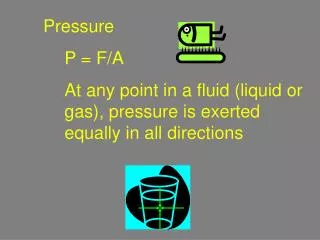
Magnet Measurement Device for MICE. F. Garnier, P-A. Giudici, F.Bergsma CERN MICE Collaboration Meeting No. 28 Absorber Systems & MICE Magnets Session 6 October 2010 technical drawings by O.Jamet. Layout. Rails. Trolley with B-sensors. Servo motor with encoder. ¼ pipe of aluminum.

E N D
Magnet Measurement Device for MICE F. Garnier, P-A. Giudici, F.Bergsma CERN MICE Collaboration Meeting No. 28 Absorber Systems & MICE Magnets Session6 October 2010 technical drawings by O.Jamet
Layout Rails Trolley with B-sensors Servo motor with encoder ¼ pipe of aluminum Cradles Tooth belt Support by adjustment screws on cradles Magnet bore Support by tripods
Disk with 7 B-sensors calibrated at 4.5 Tesla Axis of rotation 5 degree steps Magnet bore Rails ¼ pipe of aluminum Cradle 5 m
2 versions Extension disk for AFC 5m version for spectrometer solenoids 2m version for focus absorber solenoids. Extension disk to by-pass internal flange AFC Need to measure from both sides 2m version could be used to measure eventually coupling coils Irremovable flange
Single-row 10 pin connector Feet tolerance 50 µm thermistor Homogeneous field region is small => need high density => single row connector Glass cube with 3 Hall probes B-sensor card Stack of B-sensors in calibrator Double row flat- cable connector SPI-interface front back Passive backplane for B-sensor to carry double-row connector Daisy chain B-sensors
Calibration done at GHMFL Grenoble Bmax=4.5 Tesla 130 mm IMMW15 F.Bergsma
Measurement grid Disk can rotate in steps of 5 degree 180 mm sensor has to be removed for this region
DAQ + control SPI -> RS232 interface, SPI-bus with 7 slots Where to put interface: inside or outside 4 Tesla? Leave both options open DAQ program (MSVC) runs on PC (laptop) BALDOR servo engine with NextMove ESB motion controller ESB connected with CANbus to PC
STRATEGY mechanics: 1 build 5 m version , test precision 2 if precision insufficient add encoder, foresee laser tracker during measurements 3 build 2 m version DAQ: Build simple read-out for 7 B-sensors Anticipate to have interface outside high field region Accuracy: Better than 0.5 mm longitudinal +/- 0.1mm radial +/- 1 mrad directive Bx,By,Bz +/- 2 mT Check in situ with NMR Surveying done at CERN with laser tracker