Download
1 / 11
150 likes | 440 Vues
Calculation of Structure Factors. For a detailed discussion of the calculation of structure factors, see the following web site (there are many other useful discussions there too): http://www-structmed.cimr.cam.ac.uk/Course/Adv_diff1/Diffraction.html

E N D
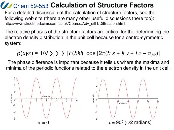
Calculation of Structure Factors For a detailed discussion of the calculation of structure factors, see the following web site (there are many other useful discussions there too): http://www-structmed.cimr.cam.ac.uk/Course/Adv_diff1/Diffraction.html The relative phases of the structure factors are critical for the determining the electron density distribution in the unit cell because for a centro-symmetric system: ρ(xyz) = 1/V ∑ ∑ ∑ |F(hkl)| cos [2p(h x + k y + l z – ahkl)] The phase difference is important because it tells us where the maxima and minima of the periodic functions related to the electron density in the unit cell. a = 90º (p/2 radians) a = 0
When the cosine waves are in phase with one another, you can determine the amplitude of the resultant wave by simply adding the amplitudes of the initial waves.
When the cosine waves are not in phase with one another, the situation becomes more complicated. The resultant wave has the same wavelength, but the amplitude is decreased and the maximum is no longer at 0 – the phase is shifted by a.
In general, for several waves: The reason for these quantities is illustrated below.
Argand Diagrams These diagrams are called Argand diagrams, where the horizontal axis is real and the vertical axis is imaginary. These end up being a much simpler way of adding waves because each wave can easily be represented as a vector. The length of each vector is fj, and the phase relative to the origin is provided by the angle (f in these diagrams, a overall in the equations I have given you). From Euler: eif = cos(f) – isin(f) Thus: exp(-inpx) = cos(npx) – isin(npx) And: exp(inpx) + exp(-inpx) = 2 cos(npx) exp(inpx) - exp(-inpx) = 2i sin(npx)
Argand Diagrams Here are some more properties of complex numbers and Argand diagrams that end up being helpful in the understanding of structure factors. In particular, notice that the phase angle can be easily determined from tan(B/A) if we know the values A and B. Also notice that to square a complex number, it must be multiplied by its complex conjugate! z = a + ib = |z| (cosa + i sina), where a is the angle between z and the real axis. |z| = (a2 + b2)1/2 = [(a + ib)(a - ib)]1/2 = (z z*)1/2 complex conjugate
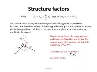
Friedel’s Law and Structure Factors In general, for several waves: As you would expect, symmetry relates certain families of planes to each other and the actual relationships between the intensities of sets of related reflections are described by Friedel’s law. Note that the intensity of a reflection is proportional to the square of the magnitude of F(hkl); i.e. I(hkl)α |F(hkl)|2 Friedel’s law asserts that:I(hkl)≡ I(-h-k-l) This is a consequence of the structure factor equation in the form: F(hkl) = A(hkl) + iB(hkl) Since cos(-a) = cos(a) and sin(-a) = -sin(a) F(-h-k-l) = A(hkl) - iB(hkl) |F(hkl)| = |F(-h-k-l)| = [A2 + B2]1/2 Note a(-h-k-l) = - a(hkl)
Friedel’s Law and Structure Factors Friedel’s law is important in terms of the actual diffraction experiment for several reasons. Primarily, the relationship reduces the amount of data that is necessary to collect. When Friedel’s law holds (there are some exceptions), the intensity of half of the reciprocal lattice is provided by the other half, thus we only need to collect a hemisphere of the reciprocal lattice points within the limiting sphere. Similar arguments can be used to deduce the relationships between the I(hkl) values for more symmetric crystal systems and thus to determine the number of independent reflections that must be collected. orthorhombic octant I(hkl) ≡ I(-hkl) ≡ I(h-kl) ≡ I(hk-l) ≡ I(-h-kl) ≡ I(-hk-l) ≡ I(h-k-l) ≡ I(-h-k-l) monoclinic quadrant I(hkl) ≡ I(-h-k-l) ≡ I(-hk-l) ≡ I(h-kl) I(-hkl) ≡ I(h-k-l) ≡ I(hk-l) ≡ I(-h-kl) But: I(hkl) ≠ I(-hkl) triclinic hemisphere I(hkl) ≡ I(-h-k-l)
Laue Groups Note that the actual diffraction pattern (with the intensities of the reflections taken into account) must be at least centro-symmetric from Friedel’s law. When this centro-symmetric requirement is combined with the actual symmetry of the crystal lattice one obtains the Laue Class or Laue symmetry of the reciprocal lattice. This symmetry is used by the data collection software, in conjunction with systematic absences, to determine the space group of the crystal. Note: a “Friedel pair” are reflections that are only related by Friedel’s law, not by crystal symmetry. Pairs of reflections that are related by the symmetry of the crystal are called “centric” reflections.
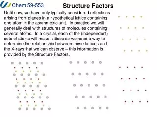
Structure Factors Note that the structure factor equations in their various forms are used to derive numerous different relationships that end up being useful for crystallography. For example, you can look up examples of the derivation of systematic absences using these equations in any of the text books I have suggested. An interesting and useful consequence of the structure factor equations is that the phases found in centro-symmetric crystals are only on the real axis, thus the phase a is either 0 or p. In a centro-symmetric crystal if there is an atom at xyz, then there must be an identical atom at -x-y-z so the structure factor equation in the form F(hkl) = A(hkl) + iB(hkl) gives: A(hkl) = f [cos2p(hx+ky+lz)+ cos2p(h(-x)+k(-y)+l(-z))] = 2 f [cos2p(hx+ky+lz)] B(hkl) = f [sin2p(hx+ky+lz) + sin2p(h(-x)+k(-y)+l(-z))] = 0 Thus: F(hkl) = 2 f [cos2p(hx+ky+lz) = A(hkl) This means that the phase is either positive or negative. This makes determining the phases of the reflections significantly easier
Structure Factors In summary, structure factors contain information regarding the intensity and phase of the reflection of a family of planes for every atom in the unit cell (crystal). In practice, we are only able to measure the intensity of the radiation, not the phase. Because of this, it is necessary to ensure that the intensity data is as accurate as possible and all on the same scale so that we can use it to determine the electron density distribution in the crystals.