Download
1 / 125
2.16k likes | 3.73k Vues
Gas Turbine Engine Theory. Course Objectives. 1. Introduction to Gas Turbine Engine Theory 2. Gas Turbine Engine Construction 3. Engine Variations and Applications 4. Gas Turbine Engine Accessory Systems. Learning Outcomes. On successful completion of this training the learner will

E N D
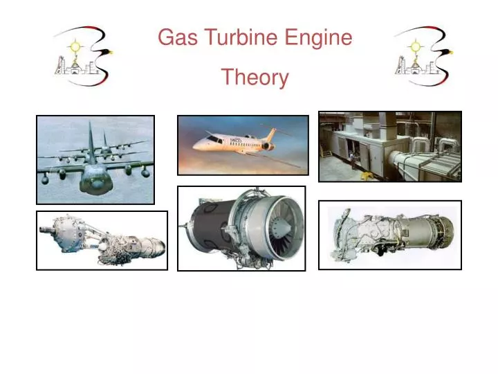
Gas Turbine Engine Theory
Course Objectives 1. Introduction to Gas Turbine Engine Theory 2. Gas Turbine Engine Construction 3. Engine Variations and Applications 4. Gas Turbine Engine Accessory Systems
Learning Outcomes On successful completion of this training the learner will be able to explain the following: • Basic operating principles and engine construction • Variations and applications of Gas Turbine Engines • Accessory systems required to operate a Gas Turbine Engine
Objectives 1. Introduction to Gas Turbine Engine Theory • Principles of Operation • History of Gas Turbine Engine Development • Basic Laws of Physics • Terms and Definitions
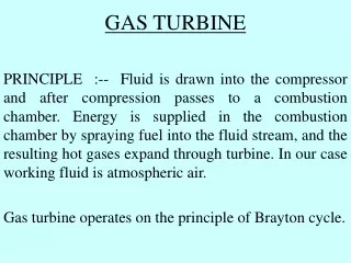
Principles of Operation • Jet propulsion: • As it applies to Gas Turbine Engines A confined substance (air) is heated, allowed to expand, and then forced to escape in a controlled manner through an orifice or nozzle. The force produced by the substance will be equal to the mass multiplied by the acceleration.
Principles of Operation • Newton's Laws of Motion: • Newton’s 1st Law A body in motion will tend to stay in motion unless acted upon by an external force. • Newton’s 2nd Law The acceleration of an object is directly proportional to the force applied and inversely proportional to it’s mass. • Newton’s 3rd Law For every action there is an equal and opposite reaction
History of Development Examples of Jet Propulsion
Jet Engines • All jet engines operate based on the principles of jet propulsion and the Newton’s 3rd Law. Jet Engine Types: • Ramjet, Scramjet • Pulsejet • Rockets • Liquid gas • Solid gas • Gas Turbine Engines • Turbojet • Turboprop/shaft • Turbofan
Ramjet Engine Rocket Engine Pulsejet Engine Jet Engines http://www.youtube.com/watch?v=pGtK8S0QRSo&feature=related
Turbojet Engine Turboprop/shaft Engine Turbofan Engine Jet Engines • Compressor (impeller) is used to compress air. • Compressed air is mixed with fuel and combusted. • Turbine extracts power from airflow to turn compressor. • Remaining airflow used to produce thrust or drive a propeller, fan, generator.
Potential Energy Kinetic Energy Terms & Definitions Energy: Two forms of energy discussed in gas turbine engine theory • Potential energy = static pressure (pressure) • Eg. Airflow at the engine inlet duct or inlet to combustor • Kinetic energy = dynamic pressure (velocity) • Eg. Combustion gases striking turbine blades
Total energy in the Venturi Tube will remain constant • Pressure then velocity must • Velocity then pressure must Airflow Characteristics Bernoulli’s Principle http://home.earthlink.net/~mmc1919/venturi.html
Divergent Divergent Divergent Divergent Passage = P V Convergent Passage = V P Convergent Convergent Convergent Airflow Characteristics
Airflow Characteristics Mass: • The amount of matter in an object. • M = W g Weight: • Considers the effect of gravity on mass. • W = M x g Density: • Measures the mass in a unit volume. Eg. Cubic inch or in3 • The denser the air the greater its weight will be given the same mass.
Airflow Characteristics Temperature: • Heat energy added to an object will increase it’s molecular activity. The opposite is true if heat energy is removed. Temperature (heat) as it effects engine mass airflow: • Hotter air is less dense as fewer molecules are contained in a given volume. • Colder air is more dense as more molecules are contained in a given volume
Airflow Characteristics Standard Day Conditions & Engine Performance: Used to evaluate an engines performance based on known conditions. Gas Turbine Engines operate in constantly changing air conditions related to pressure, temperature, airspeed, and altitude. Standard Day Conditions are used to evaluate the engines performance against the manufacturer’s established criteria. Atmospheric pressure 29.92 in Hg 100 kA Atmospheric temperature 59o F 15oC Altitude 0 feet 0 meters Humidity 0 % 0% Airspeed 0 knots 0 km/hr
Airflow Characteristics • Speed of Sound / Mach number: • The rate at which a disturbance in the air will move through it. • Air temperature will cause the speed of sound to vary. • This is due to the effect temperature has on air density. • The “MACH” number is used to express an objects speed compared to the local speed of sound (air temperature factored in) • M = V, V = velocity. • C C = local speed of sound http://www.grc.nasa.gov/WWW/K-12/airplane/atmosi.html http://www.grc.nasa.gov/WWW/K-12/airplane/shock.html
Airflow Restricted to M 1.0 or below Choked Nozzle Airflow Characteristics Note: A nozzle may be used to increase subsonic airflow to M 1.0 (turbine) or it may be used to decrease supersonic airflow to M 1.0 (engine inlet)
Objectives • 2. Gas Turbine Engine Construction • Engine Modules/Sections • Inlet • Compressor • Combustion • Turbine • Exhaust • Accessory Gearbox • Principles of Operation • Materials of Construction
Introduction Most Gas Turbine Engines are designed to reflect what is called “Modular Design”. The purpose of this is to assist the ease of maintenance by allowing certain sections or modules to be replaced with a new or overhauled one instead of replacing the entire engine. The following examples are the basic modules that make up a Turbojet engine. All other engines are derived from this basic engine design. A turbojet engine typically consists of 6 modules each of which is designed to suit the end use of the engine. • Airframe or Package inlet / engine inlet • Compressor / Diffuser • Combustor • Turbine • Exhaust • Accessory Drive
Cold Section Hot Section Introduction
Introduction Engine Station Numbering
Airframe or Package Inlet Module • Provides supply of air to the engine under all conditions • May have provisions for anti-icing • Categories: Subsonic or Supersonic (turbulence, takeoff, idle, engine rpm, temperature, altitude)
Inlet Duct - Turboprop Inlet Duct - Commercial Jet Airframe or Package Inlet Module Subsonic
Inlet Duct – Test Cell Airframe or Package Inlet Module Subsonic
Airframe or Package Inlet Module Supersonic Ducts http://www.grc.nasa.gov/WWW/K-12/airplane/mshock.html
Compressor Module Airfoil: An airfoil is a specially designed body used to create a reaction to the air that flows around it. Typical airfoil: Higher (static) pressure air on the bottom and lower (static) pressure air on the top. Total pressure will remain the same Angle of Attack: Is the angle between the airfoil chord line and the relative wind.
Compressor Module Primary Purpose: • To increase pressure of air received from the inlet to provide sufficient volume of air at the proper pressure for combustion. • Minimal rise in temperature Secondary Purpose: • Provide bleed air for engine cooling, de-icing, cabin heating, engine start Typical compressor ratios of 15-1, 300-400 lbs/s 3 types: • Centrifugal, Axial, and Axial/Centrifugal Flow
Compressor Module Centrifugal Flow • Impeller, diffuser, compressor manifold • Impeller increases air velocity and pressure • Diffuser is a series of divergent passages • Manifold is use to direct high pressure air to combustor
Compressor Module Centrifugal Flow
Compressor Module Centrifugal Flow
Compressor Module Compressor Rotor Compressor Stator Compressor Module Axial Flow • Compressor rotor, compressor rotor wheels/disks, compressor stator vanes, compressor cases. • Compressor rotor blades - increases velocity and pressure • Compressor wheels/disks control air flow and provide a means of attaching the rotors blades • Compressor stator vanes - divergent passages increase pressure • Compressor cases control air flow and provide a means of attaching the stators vanes
Compressor Module Axial Flow - Airflow
Variable Geometry Actuating Arms Stage 4 Bleed Manifold Stage 6 Bleed Manifold Variable Geometry Vanes Stationary Guide Vanes Inlet Guide Vanes Compressor Module Axial Flow - Airflow
Compressor Module Axial Flow - Multi-spool • A coaxial shaft allows for different engine designs • Maximizes engine efficiency • Responds quickly to changes in power setting
Compressor Module Axial Flow - Multi-spool 1 compressor driven by 1 turbine 2 compressors driven by 2 turbines (Free Turbine) 3 compressors driven by 3 turbines
Compressor Module Axial-Centrifugal Flow • Combines both axial and centrifugal styles • Uses best features of both • Used on many small engines, helicopter, business
Compressor Module Rotor Blade Design/Construction • Designed with a twist or stagger angle • Ensures constant airspeed over length of blade • Attached to the disk or wheel using solid, fir tree, dovetail methods
Compressor Module Stator Vane Design/Construction • Shrouds help eliminate air leakage and smooth airflow • Variable vanes may be used to improve performance
Direction of rotation Inlet Guide Vanes 1st Stage Rotor Blades Chord Line Rotor speed effect on velocity and direction Guide vane discharge air velocity and direction Resultant air velocity and direction (AOA) Mass Airflow vs Engine RPM Mass Airflow / Engine RPM
Direction of rotation Inlet Guide Vanes 1st Stage Rotor Blades Chord Line Rotor speed effect on velocity and direction Guide vane discharge air velocity and direction Resultant air velocity and direction (AOA) Mass Airflow / Engine RPM =
Direction of rotation Inlet Guide Vanes 1st Stage Rotor Blades Chord Line Rotor speed effect on velocity and direction Guide vane discharge air velocity and direction Resultant air velocity and direction (AOA) Mass Airflow = / Engine RPM
Compressor Module Stall Avoidance Techniques 1. Bleed valves to dump excess air 2. Split compressor into spools 3. Variable inlet guide vanes 4. Radical blade design • Stall consequences, load bangs, flames, smoke, possible damage to engine
Compressor Module Diffuser • Divergent to allow air to expand and slow before entering combustor • Exit guide vanes will straighten and smooth airflow • Point of highest air pressure • May utilize bleed air ports to dump excess air, heating, anti-icing
Compressor Module Diffuser
Compressor Module Diffuser
Combustion Module • Function is to add heat energy to compressed air • Combustor allows air to expand / accelerate into turbine • Temperatures may reach 3500°F 4 types: • Can • Can annular • Annular • Annular reverse flow