Download
1 / 18
180 likes | 188 Vues
Combinational Logic. Logic circuits for digital systems may be combinational or sequential . A combinational circuit consists of input variables, logic gates, and output variables. Analysis procedure. To obtain the output Boolean functions from a logic diagram, proceed as follows:

E N D
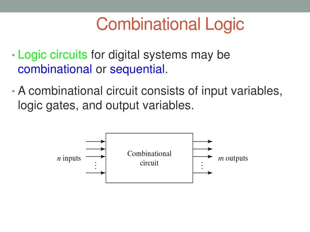
Combinational Logic • Logic circuits for digital systems may be combinational or sequential. • A combinational circuit consists of input variables, logic gates, and output variables.
Analysis procedure • To obtain the output Boolean functions from a logic diagram, proceed as follows: • Label all gate outputs that are a function of input variables with arbitrary symbols. Determine the Boolean functions for each gate output. • Label the gates that are a function of input variables and previously labeled gates with other arbitrary symbols. Find the Boolean functions for these gates.
Analysis procedure • Repeat the process outlined in step 2 until the outputs of the circuit are obtained. • By repeated substitution of previously defined functions, obtain the output Boolean functions in terms of input variables.
Example F2 = AB + AC + BC; T1 = A + B + C; T2 = ABC; T3 = F2’T1; F1 = T3 + T2 F1 = T3 + T2 = F2’T1 + ABC = A’BC’ + A’B’C + AB’C’ + ABC Fig.7.2
Design procedure • Table7-2 is a Code-Conversion example, first, we can list the relation of the BCD and Excess-3 codes in the truth table.
Circuit implementation z = D’; y = CD + C’D’ = CD + (C + D)’ x = B’C + B’D + BC’D’ = B’(C + D) + B(C + D)’ w = A + BC + BD = A + B(C + D)
4-4. Binary Adder-Subtractor • A combinational circuit that performs the addition of two bits is called a half adder. • The truth table for the half adder is listed below: S = x’y + xy’ C = xy S: Sum C: Carry
Full-Adder • One that performs the addition of three bits(two significant bits and a previous carry) is a full adder.
Another implementation • Full-adder can also implemented with two half adders and one OR gate (Carry Look-Ahead adder). S = z ⊕ (x ⊕ y) = z’(xy’ + x’y) + z(xy’ + x’y)’ = xy’z’ + x’yz’ + xyz + x’y’z C = z(xy’ + x’y) + xy = xy’z + x’yz + xy
Binary adder • This is also called Ripple Carry Adder ,because of the construction with full adders are connected in cascade.
Carry Propagation • Fig.4-9 causes a unstable factor on carry bit, and produces a longest propagation delay. • The signal from Ci to the output carry Ci+1, propagates through an AND and OR gates, so, for an n-bit RCA, there are 2n gate levels for the carry to propagate from input to output.
4-5 Decimal adder BCD adder can’t exceed 9 on each input digit. K is the carry.
Rules of BCD adder • When the binary sum is greater than 1001, we obtain a non-valid BCD representation. • The addition of binary 6(0110) to the binary sum converts it to the correct BCD representation and also produces an output carry as required. • To distinguish them from binary 1000 and 1001, which also have a 1 in position Z8, we specify further that either Z4 or Z2 must have a 1. C = K + Z8Z4 + Z8Z2
Implementation of BCD adder • A decimal parallel adder that adds n decimal digits needs n BCD adder stages. • The output carry from one stage must be connected to the input carry of the next higher-order stage. If =1 0110
4-6. Binary multiplier • Usually there are more bits in the partial products and it is necessary to use full adders to produce the sum of the partial products. And
4-bit by 3-bit binary multiplier • For J multiplier bits and K multiplicand bits we need (J X K) AND gates and (J − 1) K-bit adders to produce a product of J+K bits. • K=4 and J=3, we need 12 AND gates and two 4-bit adders.