Download
1 / 16
180 likes | 359 Vues
A Design Technique for Energy Reduction in NORA CMOS Logic. Konstantinos Limniotis, Yiorgos Tsiatouhas , Member, IEEE, Themistoklis Haniotakis , Member , IEEE, and Angela Arapoyanni , Member , IEEE. IEEE TRANSACTIONS ON CIRCUITS AND SYSTEMS

E N D
A Design Technique for Energy Reduction in NORA CMOS Logic Konstantinos Limniotis, Yiorgos Tsiatouhas, Member, IEEE, Themistoklis Haniotakis, Member, IEEE, and Angela Arapoyanni, Member, IEEE IEEE TRANSACTIONS ON CIRCUITS AND SYSTEMS page(s):2647 - 2655 , Dec. 2006 指導老師 : 魏凱城 老師 學 生 : 蕭荃泰 日 期 : 97年6月16日 彰化師範大學積體電路設計研究所
Outline • Abstract • Charge recycling concept in NORA logic • Proposed charge recycling technique • Case studies • Conclusion
Abstract • In this work, a design technique to reduce the energy consumption in no race (NORA) circuits is presented. • The no race (NORA) circuits, which is based on the charge recycling concept to reduce dynamic energy dissipation. • Calculations proved that energy savings higher than 20% can be achieved.
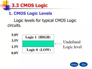
Charge recycling concept in NORA logic evaluation phase pre-charge phase VDD VDD hold 0 CLK= 1 0 0 Fig. 1. NORA logic design technique.
SW ON Fig. 2. Charge recycling concept in NORA circuits. when Cp=Cn max=0.25
Proposed charge recycling technique Vm Vn Vp Fig.3 Proposed charge recycling switch.
0.18um CMOS technology VDD=1.8V and Vtn=0.35V
, switching activity factor :
Case studies 0.18-um CMOS technology , ,
1/2 VDD VDD 0 1/2 VDD VDD 0 hold 1 0 Fig. 6. (b) Stage of the decoder after the insertion of the recycle switch and the application of the modified clocks. CLK= CLKM= 0 1 1 0
1.8% delay increase. energy-delay product reduction is 5.9%. silicon area cost is 5.7%.
Conclusion • It is based on the charge recycling approach and uses a unidirectional charge transfer topology and a new clocking scheme to allow charge recycling. • The proposed clocking scheme, the elimination of the short circuit current is achieved. • The proposed technique is characterized by insignificant delay penalty so that considerable reductions in the energy-delay product can be achieved.