Download
1 / 20
270 likes | 919 Vues
Fundamental of antenna. Welcome . Name: Mashhour j umah ID:202322165. What is an antenna?. An antenna is an electrical conductor or system of conductors used for transmission and reception of electromagnetic waves Transmission radiates electromagnetic energy into space Reception

E N D
Fundamental of antenna Welcome Name: Mashhourjumah ID:202322165
What is an antenna? • An antenna is an electrical conductor or system of conductors used for transmission and reception of electromagnetic waves • Transmission • radiates electromagnetic energy into space • Reception • collects electromagnetic energy from space
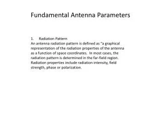
Antenna Fundamentals Radiation Patterns
Antenna Fundamentals • Relationship between antenna gain and effective area • G = antenna gain • Ae= effective area • f = carrier frequency • c = speed of light (» 3 ´ 108 m/s) • = carrier wavelength Property of R Struzak
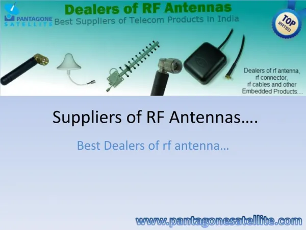
Types of antenna • Antenna types: actually there are many types of Antenna and there some of them: • 1- A Yagi antenna,also known as a Yagi-Uda array or simply a Yagi, is a unidirectional antenna commonly used in communications when a frequency is above 10 MHz This type of antenna is popular among Amateur Radio and Citizens Band radio operators. It is used at some surface installations in satellite communications systems.
Type of antenna • 2 - isotropic antenna • Radiates power equally in all directions • 3 - Dipole antennas • Half-wave dipole antenna (or Hertz antenna) • Quarter-wave vertical antenna (or Marconi antenna): The term "Marconi antenna" usually refers to a two part antenna consisting of a vertical portion and a "reflective" or "ground" portion. • 4 -Parabolic Reflective Antenna • 5-Slot antenna
monopole antenna • 6-monopole antenna: is a radio antenna that is one half of a dipole antenna combined with a right-angle ground plane of considerable length in place of its other half.
horn antenna • -7 horn antenna: is used for the transmission and reception of microwave signals. It derives its name from the characteristic flared appearance. The flared portion can be square, rectangular, or conical.
helical antenna • - 8- helical antenna is a specialized antenna that emits and responds to electromagnetic filed with rotating (circular)polarization. These antennas are commonly used at earth-based stations in satellite communications systems. This type of antenna is designed for use with an unbalanced feed line such as coaxial cable.
Antenna functions • Transmission line • Power transport medium - must avoid power reflections, otherwise use matching devices • Radiator • Must radiate efficiently – must be of a size comparable with the half-wavelength • Resonator • Unavoidable - for broadband applications resonances must be attenuated
Reflector antennas • Reflectors are used to concentrate flux of EM energy radiated/ received, or to change its direction • Usually, they are parabolic (paraboloical). • The first parabolic (cylinder) reflector antenna was used by Heinrich Hertz in 1888.
Reflector antennas • Large reflectors have high gain and directivity • Are not easy to fabricate • Are not mechanically robust • Typical applications: radio telescopes, satellite telecommunications.
Planar reflectors d • Uda-Yagi, Log-periodic antennas 2d • Intended reflector antenna allows maintaining radio link in non-LOS conditions (avoiding propagation obstacles) • Unintended antennas create interference
Receiving antenna equivalent circuit Radio wave Receiver Transm.line The antenna with the transmission line is represented by an (The venin) equivalent generator The receiver is represented by its input impedance as seen from the antenna terminals (i.e. transformed by the transmission line) VAis the (induced by the incident wave) voltage at the antenna terminals determined when the antenna is open circuited jXA jXL Rr Antenna Rl RL VA Thevenin equivalent
Power transfer • The maximum power is delivered to (or from) the antenna when the antenna impedance and the impedance of the equivalent generator (or load) are matched
Exercise Exercise ?