Download
1 / 1
10 likes | 85 Vues
START. STOP. Sector 10. Sector 11. 8 PoN + 2 BPC. Device. N. End of single measurement thread. Device. A re there any non-measured connections?. Repeat measurement cycle?. Unblock MAB of the given camera. Device. Get optical connection list from DB. N. JDBC. 8 PoN + 1 BPC.

E N D
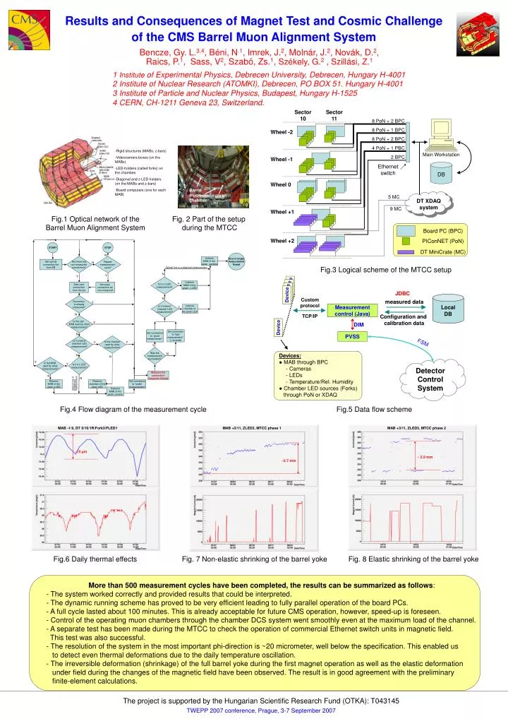
START STOP Sector 10 Sector 11 8 PoN + 2 BPC Device N End of singlemeasurementthread Device Are there anynon-measured connections? Repeatmeasurement cycle? Unblock MAB of the given camera Device Get optical connection list from DB N JDBC 8 PoN + 1 BPC Device Wheel -2 Optical line is a diagonal measurement Local DB Custom protocol measured data 8 PoN + 2 BPC N Y Y Measurement control (Java) Is it a z-LEDmeasurement? 4 PoN + 1 PBC Set connection to “bad measurement”(+ errcode) Unblock MAB of the given z-LED Y Take next connectionfrom the list Set every connection as non-measured TCP/IP Configuration and calibration data Main Workstation 2 BPC Wheel -1 DIM N Connection is alreadymeasured? Device Ethernet switch DB Y Is it a barrel chamber LEDmeasurement? Unblock chamber of the given LED Y PVSS N FSM Wheel 0 Is the cam. MAB used by othermeasurement? Y Devices: ● MAB through BPC - Cameras - LEDs - Temperature/Rel. Humidity ● Chamber LED sources (Forks) through PoN or XDAQ 5 MC Set connection to “good measurement” N DT XDAQ system Detector Control System Is the chamber used by othermeasurement? Is it a barrelchamber LEDmeasurement? Y Y 9 MC Wheel +1 Y Was themeasurementsuccessfull? N N N Is the MAB used by othermeasurement? Is it a z-LEDmeasurement? Y Y Board PC (BPC) N N Measure theconnection(separate thread) Wheel +2 PIConNET (PoN) N N Reserve MAB of thegiven z-LED Reserve chamber of the given LED Set connection to “under measurement” Optical line isa diagonalmeasurement DT MiniCrate (MC) Reserve MAB of thegiven camera Barrel muon chamber MAB More than 500 measurement cycles have been completed, the results can be summarized as follows: - The system worked correctly and provided results that could be interpreted. - The dynamic running scheme has proved to be very efficient leading to fully parallel operation of the board PCs. - A full cycle lasted about 100 minutes. This is already acceptable for future CMS operation, however, speed-up is foreseen. - Control of the operating muon chambers through the chamber DCS system went smoothly even at the maximumload of the channel. - A separate test has been made during the MTCC to check the operation of commercial Ethernet switch units inmagnetic field. This test was also successful. - The resolution of the system in the most important phi-direction is ~20 micrometer, well below the specification.This enabled us to detect even thermal deformations due to the daily temperature oscillation. - The irreversible deformation (shrinkage) of the full barrel yoke during the first magnet operation as well as theelastic deformation under field during the changes of the magnetic field have been observed.The result isin good agreement with the preliminary finite-element calculations. Results and Consequences of Magnet Test and Cosmic Challenge of the CMS Barrel Muon Alignment System Bencze, Gy. L.3,4, Béni, N.1, Imrek, J.2,Molnár,J.2, Novák, D.2, Raics, P.1,Sass, V2, Szabó, Zs.1, Székely, G.2 , Szillási, Z.1 1 Institute of Experimental Physics, Debrecen University, Debrecen, Hungary H-4001 2 Institute of Nuclear Research (ATOMKI), Debrecen, PO BOX 51. Hungary H-4001 3 Institute of Particle and Nuclear Physics, Budapest, Hungary H-1525 4 CERN, CH-1211 Geneva 23, Switzerland. • Rigid structures (MABs, z-bars) • Videocamera boxes (on the MABs) • LED-holders (called forks) on the chambes • Diagonal and z-LED holders (on the MABs and z-bars) • Board computers (one for each MAB) Fig.1 Optical network of the Barrel Muon Alignment System Fig. 2 Part of the setup during theMTCC Fig.3Logical scheme of the MTCC setup Fig.4Flow diagramof the measurement cycle Fig.5Data flow scheme MAB -1/9, DT 0/10/1R/Fork3/FLED1 MAB +3/11, ZLED3, MTCC phase 1 MAB +3/11, ZLED3, MTCC phase 2 ~15 μm ~ 2.9 mm ~2.7 mm Fig.6 Daily thermal effects Fig. 7 Non-elastic shrinking of the barrel yoke Fig. 8Elastic shrinking of the barrel yoke The project is supported by the Hungarian Scientific Research Fund (OTKA): T043145 TWEPP 2007 conference, Prague, 3-7 September 2007