Download
1 / 42
430 likes | 640 Vues
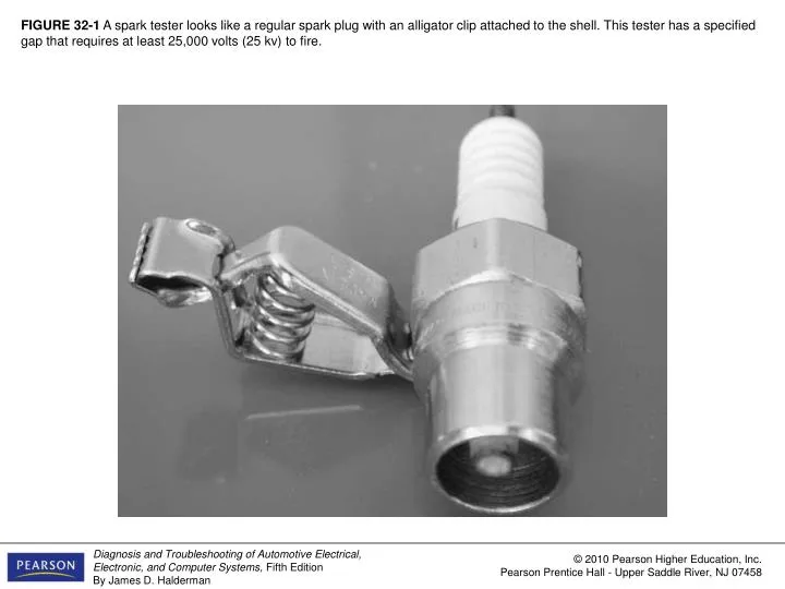
FIGURE 32-1 A spark tester looks like a regular spark plug with an alligator clip attached to the shell. This tester has a specified gap that requires at least 25,000 volts (25 kv) to fire.

E N D
FIGURE 32-1 A spark tester looks like a regular spark plug with an alligator clip attached to the shell. This tester has a specified gap that requires at least 25,000 volts (25 kv) to fire.
FIGURE 32-2 A close-up showing the recessed center electrode on a spark tester. It is recessed 3/8 in. into the shell and the spark must then jump another 3/8 into the shell for a total gap of 3/4 in.
FIGURE 32-3 Checking an ignition coil using a multimeter set to read ohms.
FIGURE 32-4 Measuring the resistance of an HEI pickup coil using a digital multimeter set to the ohms position. The reading on the face of the meter is 0.796 kΩor 796 ohms in the middle of the 500- to 1,500-ohm specifications.
FIGURE 32-5 An AC voltage is produced by a magnetic sensor. Most sensors should produce at least 0.1 volt AC while the engine is cranking if the pickup wheel has many teeth. If the pickup wheel has only a few teeth, you may need to switch the meter to read DC volts and watch the display for a jump in voltage as the teeth pass the magnetic sensor.
FIGURE 32-6 (a) The connection required to test a Hall-effect sensor. (b) A typical waveform from a Hall-effect sensor.
FIGURE 32-7 (a) The low-resolution signal has the same number of pulses as the engine has cylinders. (b) A dual-trace pattern showing both the low-resolution signal and the high-resolution signals that usually represent 1 degree of rotation.
FIGURE 32-8 A track inside an ignition coil is not a short, but rather it is a low-resistance path or hole that has been burned through from the secondary wiring to the steel core.
FIGURE 32-9 A GM type 2 distributorless ignition system (DIS) can be checked by unplugging both spark plug wires from one ignition coil and starting the engine. The spark should be able to jump the 1-in.(25-mm) distance between the terminals of the coil. No damage to the coil (or module) results because a spark occurs and does not find ground elsewhere.
FIGURE 32-10 Using a vacuum hose and a grounded test light to ground one cylinder at a time on a DIS. This works on all types of ignition systems and provides a method for grounding out one cylinder at a time without fear of damaging any component.
FIGURE 32-11 The firing order is cast or stamped on the intake manifold on most engines that have a distributor ignition.
FIGURE 32-12 Note where the high-voltage spark jumped through the plastic rotor to arc into the distributor shaft. Always check for a defective spark plug(s) when a defective distributor cap or rotor is discovered. If a spark cannot jump to a spark plug, it tries to find a ground path wherever it can.
FIGURE 32-13 Carbon track in a distributor cap. These faults are sometimes difficult to spot and can cause intermittent engine missing. The usual cause of a tracked distributor cap (or coil, if it is distributorless ignition) is a defective (open) spark plug wire.
FIGURE 32-14 Corroded terminals on a waste-spark coil can cause misfire diagnostic trouble codes to be set.
FIGURE 32-15 This spark plug boot on an overhead camshaft engine has been arcing to the valve cover causing a misfire to occur.
FIGURE 32-16 Measuring the resistance of a spark plug wire with a multimeter set to the ohms position. The reading of 16.03 kΩ(16.030 ohms) is okay because the wire is about 2 feet long. Maximum allowable resistance for a spark plug wire this long would be 20 kΩ(20,000 ohms).
FIGURE 32-17 Spark plug wire boot pliers are a handy addition to any tool box.
FIGURE 32-18 Always take the time to install spark plug wires back into the original holding brackets (wiring combs).
FIGURE 32-19 When removing spark plugs, it is wise to arrange them so that they can be compared and any problem can be identified with a particular cylinder.
FIGURE 32-20 A spark plug thread chaser is a low-cost tool that hopefully will not be used often, but is necessary to use to clean the threads before new spark plugs are installed.
FIGURE 32-21 Since 1991, General Motors engines have been equipped with slightly (1/8 in.or 3 mm) longer spark plugs. This requires that a longer spark plug socket should be used to prevent the possibility of cracking a spark plug during installation. The longer socket is shown next to a normal 5/8-in.spark plug socket.
FIGURE 32-22 An extended-reach spark plug that shows normal wear. The color and condition indicate that the cylinder is operating correctly.
FIGURE 32-23 Spark plug removed from an engine after a 500-mile race. Note the clipped side (ground) electrode. The electrode design and narrow (0.025 in.) gap are used to ensure that a spark occurs during extremely high engine speed operation. The color and condition of the spark plug indicate that near-perfect combustion has been occurring.
FIGURE 32-24 Typical worn spark plug. Notice the rounded center electrode. The deposits indicate a possible oil usage problem.
FIGURE 32-25 New spark plug that was fouled by a too-rich air–fuel mixture. The engine from which this spark plug came had a defective (stuck partially open) injector on this one cylinder only.
FIGURE 32-26 A water spray bottle is an excellent diagnostic tool to help find a intermittent engine miss caused by a break in a secondary ignition circuit component.
FIGURE 32-27 Typical timing marks. The numbers of the degrees are on the stationary plate and the notch is on the harmonic balancer.
FIGURE 32-29 (a) Typical SPOUT connector as used on many Ford engines equipped with distributor ignition (DI). (b) The connector must be opened (disconnected) to check and/or adjust the ignition timing. On DIS/EDIS systems, the connector is called SPOUT/SAW (spark output/spark angle word).
FIGURE 32-30 Typical engine analyzer hookup that includes a scope display.(1) Coil wire on top of the distributor cap if integral type of coil; (2) number 1 spark plug connection; (3) negative side of the ignition coil; (4) ground (negative) connection of the battery.
FIGURE 32-31 Clip-on adapters are used with an ignition system that uses an integral ignition coil.
FIGURE 32-32 Typical secondary ignition oscilloscope pattern.
FIGURE 32-33 A single cylinder is shown at the top and a four-cylinder engine at the bottom.
FIGURE 32-34 Drawing shows what is occurring electrically at each part of the scope pattern.
FIGURE 32-35 Typical secondary ignition pattern. Note the lack of firing lines on the superimposed pattern.
FIGURE 32-36 Raster is the best scope position to view the spark lines of all the cylinders to check for differences. Most scopes display the cylinder 1 at the bottom. The other cylinders are positioned by firing order above cylinder 1.
FIGURE 32-37 Display is the only position to view the firing lines of all cylinders. Cylinder 1 is displayed on the left (except for its firing line, which is shown on the right). The cylinders are displayed from left to right by firing order.
FIGURE 32-38 A downward-sloping spark line usually indicates high secondary ignition system resistance or an excessively rich air–fuel mixture.
FIGURE 32-39 An upward-sloping spark line usually indicates a mechanical engine problem or a lean air–fuel mixture.
FIGURE 32-40 The relationship between the height of the firing line and length of the spark line can be illustrated using a rope. Because energy cannot be destroyed, the stored energy in an ignition coil must dissipate totally, regardless of engine operating conditions.
FIGURE 32-41 A dual-trace scope pattern showing both the power and the waste spark from the same coil (cylinders 1 and 6). Note that the firing line is higher on the cylinder that is under compression (power); otherwise, both patterns are almost identical.
FIGURE 32-42 A secondary waveform of a Ford 4.6 liter V-8,showing three sparks occurring at idle speed.