Download
1 / 8
180 likes | 821 Vues
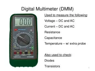
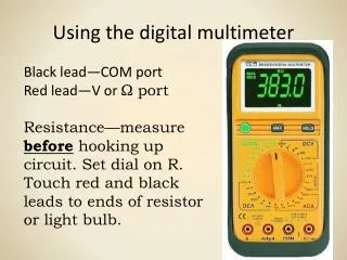
Using the digital multimeter. Black lead—COM port Red lead—V or Ω port Resistance—measure before hooking up circuit. Set dial on R. Touch red and black leads to ends of resistor or light bulb. Using the digital multimeter. Black lead—COM port Red lead—V or Ω port

E N D
Using the digital multimeter Black lead—COM port Red lead—V or Ω port Resistance—measure before hooking up circuit. Set dial on R. Touch red and black leads to ends of resistor or light bulb.
Using the digital multimeter Black lead—COM port Red lead—V or Ω port Voltage—measure while circuit is turned on. Touch red and black leads to ends of resistor or light bulb. If negative, switch leads.
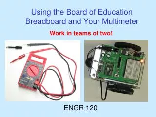
Using the power supply • Connect red and black power supply leads to the correct DC terminals on the power supply. • Set voltage to 3 volts MAXIMUM. It blows light bulbs otherwise. • Reset button on front if light turns red. • Copy images on board for connection in parallel and series.
Series circuit procedure • Solve for Req. • Use V and Req to solve for current—I. • Use I and the individual resistances to solve for V across each resistor. • Measure V across each resistor.
Parallel circuit procedure • Use V to determine voltage drop across each resistor. • Measure voltage drop across each resistor.
Series/Parallel circuit procedure • Determine Req for parallel portion of circuit. • Add the value of the series resistor to the Req. • Measure voltage drops across each resistor. • Calculate current.
Capacitance of circuits lab • Use multimeter to determine voltage of battery and resistances of two resistors. • Connect VI sensor to USB link and computer. • Set up equipment as indicated on lab handout. • Collect data for 1 resistor and 1 capacitor. • Repeat for three other arrangements. • Analyze charge and discharge graphs.
Capacitor charging and discharging You will be determining time to charge and discharge the capacitor(s) and comparing these for different arrangements.