Download
1 / 13
420 likes | 688 Vues
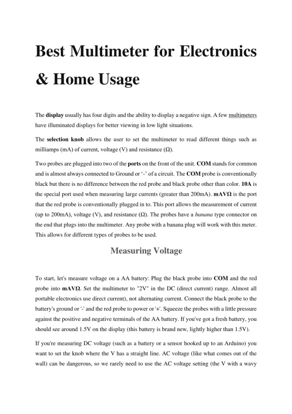
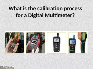
Digital Multimeter. What is a Digital Multimeter?. A digital multimeter measures AC / DC voltage, resistance, and current in an electric circuit. It is highly accurate and displays an LCD number readout. Test Leads. Test leads are used to connect the multimeter to the circuit to be tested.

E N D
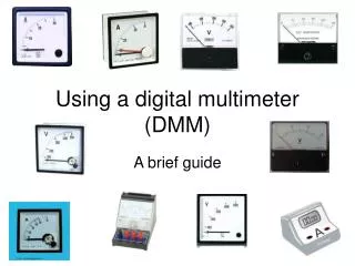
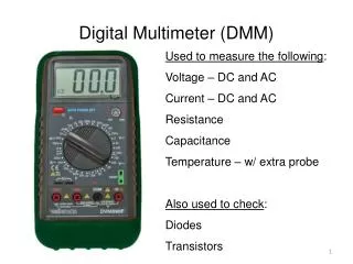
What is a Digital Multimeter? A digital multimeter measures AC / DC voltage, resistance, and current in an electric circuit. It is highly accurate and displays an LCD number readout.
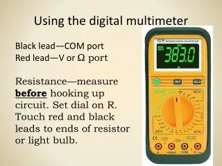
Test Leads Test leads are used to connect the multimeter to the circuit to be tested.
Function/Range Switch DC Voltage AC Voltage Battery Test Resistance DC Current Continuity Test
Voltage Meter The voltmeter is used to measure the voltage potential across a component in an active circuit. It can be used to measure either DC or AC voltages. AC voltage can ONLY measure sinusoidal (SINE) waveforms.
Test Lead Connections - Voltage Plug the RED test leadinto the jack labeled V/ and the BLACK test lead into the jack labeled COM (common).
Ohmmeter The ohmmeter is used to measure the resistance of a component. POWER CANNOT be applied to the component being tested. The ohmmeter actually applies a small voltage and uses Ohm’s law to calculate the resistance from the measured current.
Test Lead Connections - Resistance Same As Voltage Measurement
Ammeter • The ammeter is used to measure the current through a component in an active circuit. • It can be used to measure only DC current. • Some multimeters can also measure AC current.
Test Lead Connections - Current Plug the RED test lead into the jack labeled mA for milliamps or into the jack labeled 10A for circuits with high current levels. Plug the BLACK test lead into the jack labeled COM. Be certain to select the range according to the test lead connections. Observe proper polarity.
Basic Instructions • Be sure the test leads are connected appropriately for the intended measurement. • Turn the meter’s Function/Range switch to the function (ACV, DCV, DCA or ) to be measured. • Select a range which is higher than the expected value. • Connect the test leads to the circuit/component being tested. Observe proper polarity. • Turn the meter’s Function/Range switch to reduce the range and increase the accuracy. • Record results. • Remember to turn the power OFF when finished.
Special Functions • Continuity Tester • Used to test the continuity between two points. Will produce an audio tone. • Diode Tester • Used to test the resistance in a diode for forward bias and reverse bias. • Battery Tester • Used to test 9 volt and 1.5 volt (AAA,AA, C, D) batteries.
If the Meter Malfunctions : • Check meter’s battery • Review instructions to make sure all the meter’s settings are accurate for the type of testing being conducted • Check to see if test leads are broken or not connected properly • Inspect and test the fuse