Download

1 / 57
660 likes | 993 Vues
The Digital Multimeter. Science Learning Center University of Michigan – Dearborn Modified from a presentation written by Dr. John Devlin by: Donald Wisniewski, Dawn Wisniewski, Huzefa Mamoola, Shohab Virk, Saadia Yunus

E N D
The Digital Multimeter Science Learning Center University of Michigan – Dearborn Modified from a presentation written by Dr. John Devlin by: Donald Wisniewski, Dawn Wisniewski, Huzefa Mamoola, Shohab Virk, Saadia Yunus Under the direction of: Dr. Ruth Dusenbery, Dr. Paul Zitzewitz and Mr. Henry Povolny With funds from the Office of the Provost, UM-D, and NSF CCLI grant # DUE 9952827 to RD and PZ.
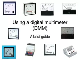
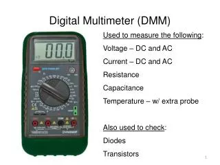
Quick Overview • The digital multimeter is one of the most versatile instruments, containing three different meters in one. • 1. A voltmeter measures the electrical potential across a device (in volts). • 2. An ammeter measures the amount of electrical current through a device (in amperes, or amps). • 3. An ohmmeter measures the electrical resistance of a device (in ohms).
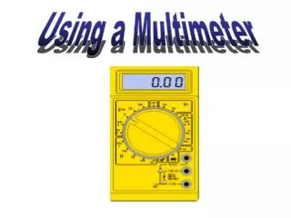
Digital Multimeter Layout • The top portion of the meter contains the digital readout area, which resembles the digital display of many pocket calculators. • Below the digital readout is a large gray knob, called the FUNCTION switch. This switch determines which function the multimeter will perform (voltmeter, ammeter, or ohmmeter).
Function Switch • There are eight positions to choose from on the function switch. • The first is OFF. The meter should always be returned to this position when not in use. • In general, the three V markings measure voltage, the next measures electrical resistance, the one marked |-))) checks for continuity, and the last two read AC and DC currents.
Function Switch - Voltage • The V~ (*) is set to measure alternating-current voltages, or simply AC voltage. • V= (*) is for direct current voltage, or DC measurements. • 300mV= (*)is used to measure low voltages of direct current in the millivolt (mV) range. * * *
Function Switch - Ohms/Amps • The position (*) is normally used to measure electrical resistance (in ohms). • The |-))) position (*) is for certain applications that will not be covered here. • A~ (*) is used to measure AC current (in amps). • A= (*) is used to measure DC current (in amps). * * * *
Starting Up • When the digital multimeter is first turned on, it will go through a self-analysis of its battery and its internal circuits. • While this is proceeding, the meter will light up almost all of the digital segments including a tiny battery symbol in the upper left hand portion of the display. • If you turn it on and it does not look like the image below, notify the SLC personnel.
Summary:The Digital Multimeter Function Switch • V~ for AC voltage • V= for DC voltage • 300 mV for low DC voltages (millivolts) • A~ for AC current • A = for DC current • for resistance • |-))) for continuity (not used in this module)
Voltage Measurements • This first series of measurements will be of DC voltages. • Turn the function switch to the V= position to read DC voltages.
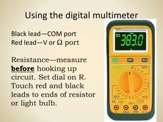
The connections to devices such as batteries or resistors are made via the two terminals on the lower right of the base of the meter. • Connect a long red test lead to the red input terminal on the meter (labeled V) and a long black lead to the black input terminal (labeled COM for common terminal). • You will now be ready to begin making measurements. Start by measuring the electrical potential difference of the battery in your circuit box.
Circuit Box • The battery is installed between the terminals labeled A and B at the left-hand side of the box. • Terminal A is at a higher potential with respect to terminal B.
To measure the potential across the battery, connect the red test lead from the meter to point A on the circuit box, and the black test lead to B. • Read the value on your display. You should obtain a value of about 9 volts, since that is the potential of the battery that powers the circuit boxes. • The type of voltage is indicated by ‘VDC’ to the right of the number displayed, which means ‘volts across a direct current circuit’.
Review of Method • We first set the function switch to the desired position (V= in this case). • Then we connect the long leads to the proper terminals of the meter. • Lastly, we connect the meter across the device in the circuit and read the display.
Determining Polarity • Leave the Function switch in the position just used, but disconnect the test leads from the circuit box. You will now reverse the connections of the long leads to the circuit box.
Connect the red test lead to terminal B on the board, and the black test lead to terminal A. • Notice the display shows nearly the same numerical value, but now has a negative (-) sign in front of it. The multimeter not only measures the magnitude of the voltage, but it also senses which terminal is at the higher potential. • Positive readings indicate that the red terminal is at the higher potential,while negative readings indicate that the black (or COM) terminal is at higher potential.
Schematic Circuit Diagram • This is a schematic (or abstract) circuit diagram. Do not worry if you have not seen this before. It is really quite common and will be explained in detail in your physics course this term. We will just give you a brief introduction to such diagrams.
The device between points C and D is a resistor. A resistor reduces electric potential when there is a current through it. • Your circuit box contains a battery and 3 resistors (R1,R2,R3) that are all soldered in place and connected to terminals. Since the box contains no internal wiring, you will have to connect these devices in a closed circuit.
Connect a short wire from point A to point C on the circuit board. • Then connect another short wire from point D to point E. • Finally, connect a third short wire from point F to point B. • You have just set up a simple series circuit which includes a battery and two resistors connected in series.
Measuring Voltage • Check to see if your meter is still set to the V= position, and the leads are disconnected from the box. • Now, connect the red test lead to point A, and the black to point B. Record your results as VAB, the voltage between points A and B, that is the battery voltage.
Next, disconnect the two meter leads from the circuit box. • Now place the free end of the red test lead to point C and the free end of the black test lead to point D. • Because the meter is now connected across resistor R1, we will be measuring the potential difference across it. Record this value as VCD.
Now disconnect the two leads from the box, and reconnect the red lead to point E and the black lead to point F. • This configuration measures the value of potential across resistor R2. Record your result as VEF.
Add the voltage results for VCD and VEF. • The loop law states that the sum of potential changes around a circuit is zero. In this circuit the loop law gives the following equation. • VCD + VEF = VAB • If this rule does not hold within 10% of your measurements, you have probably measured something wrong. If so, redo the measurements. • When you are finished, disconnect all your wires and turn the meter off.
Summary of Voltage Measurements • Measuring DC Voltage: • Set Function switch to V=. • Connect long red lead to V terminal. • Connect long black lead to COM terminal. • Connect the leads across the device. • Read the meter and record result in volts.
Current Measurements • When measuring electrical currents through devices, it is important to remember that the ammeter must be connected in an entirely different fashion from that used for voltage measurements. • It MUST be connected in series with the circuit.
Diagram of a Simple Circuit • The device between points A and B is a battery. • The device between C and D is a resistor. • In this circuit, the battery will cause a current, or flow of electric charge, to pass out one end of the battery, through the resistor and into the other end of the battery. The current direction is represented by the arrows around the circuit. We will use the letter ‘I’ to designate the current.
Assemble this circuit with the circuit box. Connect a short wire from point A to point C and then another short wire from D to B. This completes the circuit with the battery and resistor R1.
Set the FUNCTION switch to the A= position. • Connect a black lead to the COM terminal at the lower right. • Connect a red lead to the 300mA at the lower left corner of the meter. We use this terminal for low current (milliamp range) measurements only. This will be used for all measurements using this circuit box. If we needed to measure larger currents, we would use the 10A terminal instead. • In order for the ammeter to be able to measure ‘I’, we must have this current pass through the ammeter. We want the current to go, from the battery, into the multimeter through the red lead and exit through the black lead.
Measuring the Current I • Disconnect the end of the short lead from point C and join the free end of the short lead to the long red lead from the multimeter. These connected leads remain hanging free, unattached to any of the terminals on the circuit box. • Connect the long black lead of the multimeter point C to complete the electrical circuit. • The meter should read between 8.0 mA and 10.0 mA (that is, within 10%)
Note • We have temporarily interrupted the current through the resistor and forced that current through the meter before going through the resistor. The current through the meter is the same as that through the resistor. The ammeter is connected in series with the resistor. • Would you have obtained the same result if you had measured the current out of the resistor? Try it. • All current measurements are to be performed in this manner.
Schematic diagram showing a current measurement • Open up the circuit at the point of interest and connect the meter between the open points. The ammeter is indicated by a circle with the letter A inside of it.
Summary of Current Measurements • Set the function switch to A=. • Connect the long leads to the 300 mA and the COM terminals. • Connect the meter in series with the device being measured by opening up the circuit and inserting the meter between the open points. • Read the display and record the result. When the 300 mA terminal is used, the units of your results are milliamps.
Let’s try a more complicated circuit. • Before you begin, disconnect all of your previous wiring. • Place a short lead between points A and C on your board. • Place another short lead between D and E, and then another one between E and G. • Finally connect a wire from point H to point F and then another wire from F to B.
Your wiring should look like this. • Note that there are double plug connections at points E and F. • Ask yourself: How would the meter have to be connected to the circuit board in order to properly measure all of the current that passes through resistorR2 only?
The correct answer is that the circuit would have to be opened up at point E and the meter connected between the open points. • The current into point E goes to R2. If we insert the meter at this point all of the current through R2 will first go through the ammeter.
Now, connect the meter in this fashion, by removing both of the plugs that go into point E and connecting both of them to the long, red meter lead. This combination of 3 plugs will not be attached to anything else. • Finally, connect the long, black meter lead to point E to complete the circuit. • Your reading should be between 2.1 and 2.7 mA for the current through resistor R2.
Before measuring the current through the 3rd resistor, disconnect the 2 meter leads and return the 2-plug pair to point E as before. This restores the circuit to its original configuration. • How would you connect the meter to the circuit to measure the current through circuit R3?
The correct answer is shown diagrammatically. • Open up the circuit at point G. • Connect the long red meter lead to the end of the single, short wire from E. • Connect the long black meter lead to point G. Note that the free end is a double plug.
In this configuration, all of the current through the meter will also have to go through R3. • Read the display to find the value of the current. Record this result as I3. • Your answer should be between 1.4 and 1.8 milliamps (mA).
After recording your value, disconnect both meter leads from the circuit box and return the end of the short lead to point G as before. • Now we shall measure the current through resistor R1. • How would you would do this?
The answer is: Open the circuit at resistor R1. • Open the circuit at point C by disconnecting the short lead at point C. Connect the long red meter lead to the end of the short lead and connect the long black meter lead to point C. • Note that the current through R1 will now be the same as through the meter. Double check your wiring, and record the value obtained for the current as I1.
Your meter should read between 3.6 and 4.4 mA. • Disconnect both meter leads from the circuit and return the end of the short wire to point C to restore the original circuit’s configuration.
A second important circuit law says that the current through resistor R1 is equal to the sum of the current through resistor R2 and R3, or I1 = I2 + I3 • Check your numbers to see if this holds for your case. The agreement should be within about 10% uncertainty. • If you do not obtain this result, measure I1, I2, I3 again, being very careful with your connections.
Current Through the Battery • To measure the current through the battery, we perform the same procedure as for the resistors. • We open the circuit at the battery terminal and insert the meter between the open points. One possible connection is as follows:
Disconnect the wire at point B, and connect that wire to the long red meter lead. Connect the long black meter lead to point B. • Record this value as IB. For this particular circuit:IB = I1current through battery is the same as current through resistor R1. • If this is not the case for you, go back and measure I1 and IB again.
General Procedure for Measuring Electrical Currents. • First, set the function switch to A= in order to measure DC currents. • Second, connect the long leads to the 300mA and the COM terminals on the multimeter if you are measuring milliamp currents. • Third, connect the meter in series with the device by opening up the circuit at the device and inserting the meter between the two points so that all of the current going through the meter also goes through the device. • Fourth, read the value and record the results.
Resistance Measurements • The final portion of this study unit will be concerned with resistance measurements. Electrical resistance is an intrinsic property of almost every electrical device and is measurable by the multimeter. • The basic unit resistance is the ohm. When the multimeter is used to measure electrical resistance, it is called an ohmmeter. • SYMBOLS FOR RESISTANCE UNITS • for ohms • k for kilohms • M for megohms
Preparations forResistance Measurements • Disconnect all wiring from the meter and circuit box. • Individual resistors must be measured separately from any other device in the circuit. • All power sources must be disconnected when taking resistance measurements.
Turn the function switch to the position. You will use this position for all of your resistance measurements. • In this position, the display will show an “O.L.” reading when first turned on. This indicates that there is an “over load” or off scale resistance. This occurs when the resistance is higher than the meter is capable of reading, such as when no device is connected. • The long leads must also be connected properly to measure resistance. The long red lead must be connected to the V terminal, while the long black lead must be plugged into the COM terminal.
Please note that these are the same connections that were used when recording voltage readings. • Once the “O.L.” reading has been obtained and the long leads are attached properly, you are ready to begin making resistance measurements. • These measurements are made by placing the leads across the resistor to be measured.
Note that while measuring either voltage or resistance, the meter is connected across or in parallel with the device. • For example, connect the red test lead to point C on your circuit board, and the black test lead to point D to measure the resistance of R1. • Within a 10% uncertainty range, R1 measures 1000 ohms.