Download
1 / 48
700 likes | 977 Vues
CHAPTER 4. GROUNDING AND GROUND GRID DESIGN. Defining Design Objective Grounding system Equipment grounding System Grounding Ground rod and Grounding electrode 2. Soil resistivity and Ground Resistance Measurement Soil Characteristic Resistivity Measurement

E N D
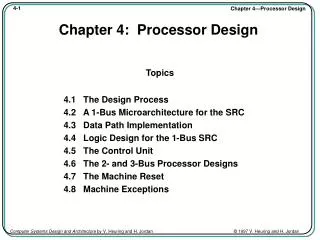
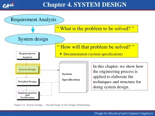
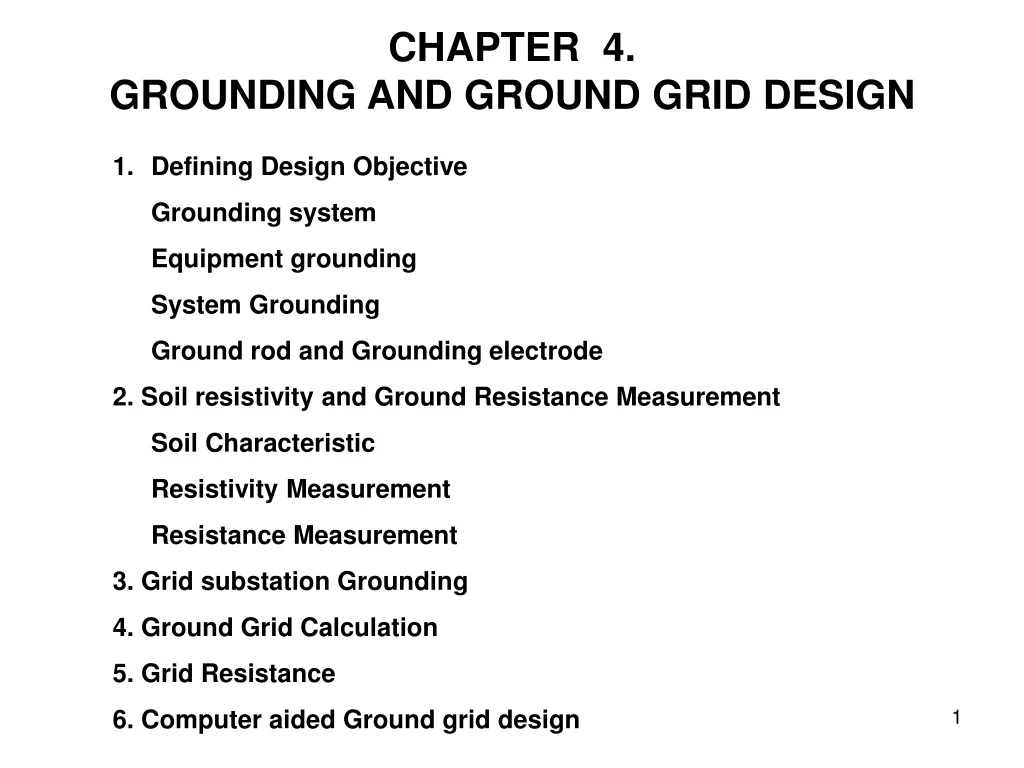
CHAPTER 4. GROUNDING AND GROUND GRID DESIGN • Defining Design Objective • Grounding system • Equipment grounding • System Grounding • Ground rod and Grounding electrode • 2. Soil resistivity and Ground Resistance Measurement • Soil Characteristic • Resistivity Measurement • Resistance Measurement • 3. Grid substation Grounding • 4. Ground Grid Calculation • 5. Grid Resistance • 6. Computer aided Ground grid design
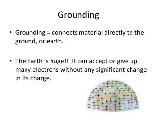
Grounding System (IEEE) as a conducting connection, whether intentional or accidental by which an electric Circuit or equipment is connected to the earth. Bonding is intentional electrical interconnecting of conductive path in order to ensure common electrical potential between the bounded parts. Equipment Grounding is interconnecting all non current carrying metal part (Body) of an electrical power system, and then connecting the interconnected metal parts to the earth. System grounding is the process connecting neutral point of system equipment to ground.
The reasons for grounding : • Personal safety by limiting potentials between • all non-current-carrying metal parts of electrical power system. • Personal safety and control of electrostatic discharge (ESD) • by limiting potentials between all non current-carrying metal • parts of an electrical power system and the ground. • To provide a low-impedance fault return path to the power • source to facilitate the operation of over current device • during the ground fault.
System Grounding: • Un Grounded System • Grounded System • - Solid grounding • - Resistance grounding • - Reactance grounding • - Ground fault neutralizer • - Distribution Transformer, etc • There is no one best system grounding method. In • choosing among the various options, the designer • must consider the requirements for safety, continuity • of service, and cost.
Ungrounded means that there is no intentional Between a current-carrying conductor and ground Solidly grounded means that an intentional zero impedance Connection is made between a current-carrying conductor and ground. Impedance-grounded means that an intentional impedance Connection is made between a current-carrying conductor and ground.
Criteria of System Grounding • Low Resistance : Ro 2 Xo and IFG = (10% - 25%) I3Ø • High Resistance : Ro Xco/3 and IFG is small • Effective X0 X1 and IFG > 60 % I3Ø 3 X1 ; Ro • Reactance X0 10 X1 and IFG = (25% - 60 % ) I3Ø
The basic reasons for system neutral grounding • To limit over voltage • To limit electric potential difference • To isolate faulty equipment and circuits • To provide low-impedance return path from the • Load back to the source and improve fault protection. • To hold system neutral point equal ground point
Ground Rod and Grounding Electrode ? Ground rod is an electrode rod buried in the earth for purpose of grounding systems. Grounding conductor is conductor that connect the grounding system to earth for purpose to keep the entire grounding system at the earth potential. Grounding electrodeis a conductor can be as wires/rod, strips, plates in intimate contact with the earth for the purpose of providing a connection with the ground grounding and bonding.
Ground rod made of : Ion or steel rods must be at least 5/8 in (15 mm) diameter; Copper-clad stainless-steel, or stainless steel-clad rod must be at least ½ -in (12 mm). Rods should be driven to at least 8 ft (2.45m). If a driven rod hits a rock bottom, the depth may < 8 feet. • Part of a Ground electrode system available in a facility, • Metal underground water pipe • Metal frame of building or structure • Concrete-encased electrodes. • Ground encircling a building.
The main factors that influence the resistance are the number of rods (paralel) , resistivity of the soil and the length. Formula resistance of a rod of length L and diameter d, resistivity soil ρ Ohm
Soil Resistivity • Soil resistivity is one of the most important factors, • in designing, grounding system of a substation. • The characteristic of the soil resistivity are primarily • affected by: • Soil type (size, variability and density), • Moisture • Temperature • Salt content • Compactness
Effect of salt, moisture, and temperature on Soil resistivity
Soil Resistivity Measurement • Wenner Method • Schlumberger-Palmer Method • i). Wenner arrangement (Equally Spaced). • Spaced a distance of a meters apart. • Driven rod to a depth not normally exceeding 0.1a • (about 0.3 meters) • Outer probes are connected to the current • terminal (C1and C2) • Inner probes to the potential terminals (P1 and P2).
The Wenner soil resistivity measurement arrangement (d<<a), then the apparent resistivity : ρ = 2 aR
ii) Schlumberger-Palmer (Unequally-spaced). Similar to Wenner, except that the inner (voltage) probe spacing is varied independently of the current probe spacing. If the depth of burial of the electrodes b is small compared to their separation d and c, = 2 Measured resistivity can be calculated aR
Ground Resistance Measurement. Normally using The fall of potential method is the most common the three-point technique.
Resistance of a rod of length L (m) and diameter d (m) in uniform soil of resistivity ρ(ohm-m) Ohm • Grid Substation Grounding • Two main design goals to be achieved • To provide means to dissipate electric currents into the earth • without exceeding any operating and equipment limits. • To assure that a person in the vicinity of grounded facilities is • not exposed to the danger of critical electric shock.
There are two conditions that person within or • round the substation may be experience • Touch voltage • Step voltage A touch voltage is normally considered a hand to foot or a hand to hand contact; A step voltage creates a path through the legs from one foot to the other.
Exposure to touch voltage Touch voltage, Etouch = Ib (RB + Zth ) The resistance of two feet in parallel Zth = Rf / 2 Zth = Rf / 2 = 1.5 s Touch voltage Circuit Equivalent
Exposure Step voltage The step voltage Estep= Ib( RB +Zth) The Thevenin equivalent Impedance for 2 feet Zth = 2 Rf = 6 ρS Step Circuit Equivalent
Permissible Body Current Limit Dalziel concludes of all men could withstand, without ventricular fibrillation, IB = A IB : rms magnitude of the current through the body, A ts : duration of the current exposure, sec k : 0.116 for a 50 kg person and 0.157 for a 70 kg person. based on test in the range of 0.03 to 3.0 second duration
Table limitations of the electric currents flow through the body
Permissible Step and Touch Voltages (Volt) Step voltage for the body 50 kg and 70 kg, respectively If no protective surface layer is used, then Cs =1 and ρs = ρ.
Touch voltage for the body 50 kg and 70 kg, respectively : Soil resistivity at the surface, Ohm-m Cs : reduction factor for derating the nominal value of ts : Fault clearing time, seconds.
Steps of grid calculation analysis: • Investigation of soil characteristics • Determination of maximum ground fault current • Preliminary design of the ground system • Calculation of resistance of the ground system • Calculation of step voltage at periphery • Calculation of internal step and touch voltages • Refinement of preliminary design.
The maximum grid current IG. IG = Sf If where IG : Symmetrical ground fault current (3I0), A If : Rms value of symmetrical fault current, A Sf : Ratio of grid current to fault current. The maximum grid current IGM = Df IG Df is the decrement factor for the fault duration.
A single line to ground fault, A double line to ground fault, X1, X2 and X0 are Positive sequence reactance, Negative and Zero, respectively.
Selection of Conductor Conductors are used for grounding system, grid conductors, connections, connecting lead, and all primary electrodes must be adequate criteria as below; i). Have sufficient conductivity ii). Resist fusing and mechanical deterioration under short circuit. iii).Be mechanically reliable and rugged to a high degree. iv).Be able to maintain its function even exposed to corrosion or physical abuse
Conductor materials may be used: • Cooper is used for grounding. • Copper–clad steel is used for underground rods and • occasionally for grid conductors, especially where • theft is a problem. • Aluminum is used for ground grids less frequently. • Steel can be used for ground grid conductor and rods.
The calculation tolerable Step, Touch, and mesh voltage based up on IEEE standard 80-1986. Vstep = KS Ki (IG / L) Ki = 0.172 N + 0.656 L = Lc + 1.15 LT (with ground grid and rods) LC : total length of the ground conductor, m LT : total length of the ground rods, m D : spacing between parallel conductors, m h : depth of the ground grid conductors, m
The mesh voltage tends to be highest in the mesh rectangle nearest to the perimeter. d : diameter of the grid conductor, m. h : depth of grid
The ground resistance of grounding grid, R = R : substation ground resistance, : soil resistivity, A : area of the grounding grid m2 According to Savarack Equation,
Computer Aided Ground Grid Design The purpose this program is to determine mesh voltage, allowable step, touch voltages and grounding resistance of substation grid. Design of the grounding resistance of substation grid said to be requirement adequate if the mesh and touch voltages from calculation result less than the step and touch voltages tolerable. Vtouch < V mesh Vstep < V step tol
The required data for the program for analysis/design • The soil resistivity at the substation location • Fault duration Current division factor • System impedance • Line to line voltage at worst-fault location • Crushed rock resistivity • Thickness of crushed rock surface • Depth of grid • Span distance of conductor • Available ground area • Conductor type in use • Fault Clearing
Improving The Performance of The Grounding Grids • Increasing the grounding area; the most effective way to • decrease ground resistance is by increasing the area • occupied by the grid. • Improvement of gradient control; If mesh voltage is higher • than the allowed touch voltage, a modified grid can be • designed by subdividing the meshes. • Addition of a relatively high resistance surface layer. • A layer of crushed rock can be added on the surface of • the substation to increase the resist.in series with the body. • The available fault current magnitude may be reduced by • connecting overhead ground wires of transmission lines. • Limiting of short-circuit current to the ground grid.
Assignment A grid substations have parameter are given as below Number of parallel conductor, n = 16 Soil resistivity, ρ = 750 ohm-m ρ S= 3,000 ohm-m Fault current, IG = 1,200 A and clearing time, t = 0.75 sec. Total length of conductor, L = 1,600 m Conductor spacing in parallel, D = 4 m Conductor diameter, d = 0.016 m Depth of grid conductor, h = 0.8 m Body resistance is 1,000 ohm (i) Calculate mesh voltage and step voltage (ii) Calculate allowable step voltage and touch voltage
Example 1. A grid substations have parameter are given as below Number of parallel conductor, n = 16 Soil resistivity, ρ = 750 ohm-m ρ S= 3,000 ohm-m Fault current, IG = 1,200 A and clearing time, t = 0.75 sec. Total length of conductor, L = 1,600 m Conductor spacing in parallel, D = 4 m Conductor diameter, d = 0.016 m Depth of grid conductor, h = 0.8 m For the above condition, the values of factors such as Km = 0.3695, Ki = 3.042 , and Ks = 0.4014. Body resistance is 1,000 ohm (i) Calculate mesh voltage and step voltage (ii) Calculate allowable step voltage and touch voltage