Download
1 / 23
240 likes | 263 Vues
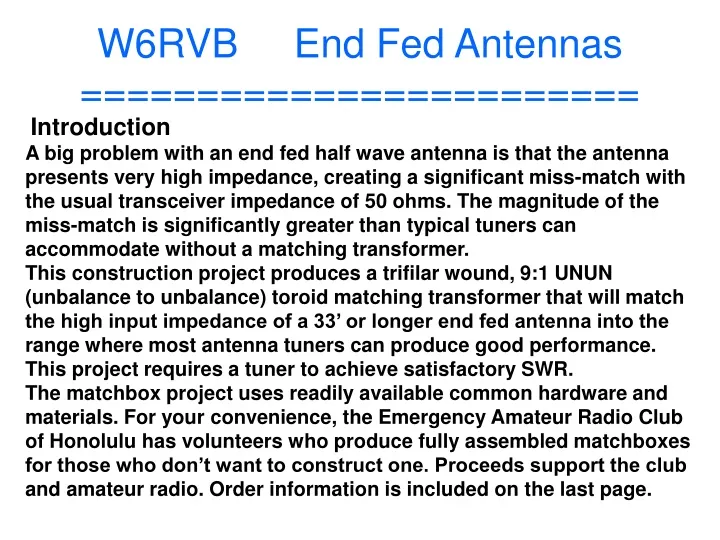
W6RVB End Fed Antennas ========================. Introduction

E N D
W6RVB End Fed Antennas======================== Introduction A big problem with an end fed half wave antenna is that the antenna presents very high impedance, creating a significant miss-match with the usual transceiver impedance of 50 ohms. The magnitude of the miss-match is significantly greater than typical tuners can accommodate without a matching transformer. This construction project produces a trifilar wound, 9:1 UNUN (unbalance to unbalance) toroid matching transformer that will match the high input impedance of a 33’ or longer end fed antenna into the range where most antenna tuners can produce good performance. This project requires a tuner to achieve satisfactory SWR. The matchbox project uses readily available common hardware and materials. For your convenience, the Emergency Amateur Radio Club of Honolulu has volunteers who produce fully assembled matchboxes for those who don’t want to construct one. Proceeds support the club and amateur radio. Order information is included on the last page.
W6RVB End Fed Antennas======================== This construction project produces a trifilar wound, 9:1 UNUN (unbalance to unbalance) toroid matching transformer that will match the high input impedance of a 33’ or longer end fed antenna into the range where most antenna tuners can produce good performance. The finished product looks like this: Long Wire Ant 9:1 UNUN --- Coax to rig --
W6RVB End Fed Antennas======================== Schematic of a 9:1 UNUN (NOT a BALUN!):
W6RVB End Fed Antennas======================== What is the impedance ratio?
W6RVB End Fed Antennas======================== Matchbox Parts List 1 small plastic enclosure and cover 1 powdered iron toroid T106 -2 or larger 3 24” pieces of 22 gauge solid insulated copper wire in red, green, and black 2 6/32” x ½” machine screws and nuts 2 #6 lock washers 1 10-24 x ¾” machine screw and nut 2 #10 flat washers 1 #10 lock washer 1 #10 wing nut 2 #10 wire lugs 1 #6 wire lug 1 SO-239 panel mount connector 1 33’ 20 gauge insulated stranded wire antenna Preparing the MATCHBOX Plastic Enclosure Start the project by drilling one 5/8” hole and two 6/32” holes for mounting the SO-239 coax connector on the lower side of the enclosure. Use the connector as a guide to mark for accurate drilling of smaller holes. Next, drill a 3/16” hole in the upper right side of the box for mounting the antenna connector.
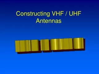
W6RVB End Fed Antennas======================== ‘Matchboxes’ come in many sizes/shapes:
W6RVB End Fed Antennas======================== ‘Matchboxes’ come in many sizes/shapes:
W6RVB End Fed Antennas======================== ‘Matchboxes’ come in many sizes/shapes:
W6RVB End Fed Antennas======================== Original Schematic of the Johnson – Viking KW Matchbox Tuner
W6RVB End Fed Antennas======================== Matchbox Parts List 1 small plastic enclosure and cover 1 powdered iron toroid T106 -2 or larger 3 24” pieces of 22 gauge solid insulated copper wire in red, green, and black 2 6/32” x ½” machine screws and nuts 2 #6 lock washers 1 10-24 x ¾” machine screw and nut 2 #10 flat washers 1 #10 lock washer 1 #10 wing nut 2 #10 wire lugs 1 #6 wire lug 1 SO-239 panel mount connector 1 33’ 20 gauge insulated stranded wire antenna Website: http://www.earchi.org/
W6RVB End Fed Antennas======================== Matchbox performance will be determined by two factors: The length of the antenna wire, and the capability of the tuner. The length of the wire should generally be between 22 and 60 feet for best performance. Longer wires may have excessive impedance for tuners to properly match. Wires shorter may not radiate effectively. A 30 foot insulated 18 gauge stranded wire antenna and connecting lug should meet most requirements. Experience has shown that most external tuners and many internal tuners will tune 80–6 meters with an antenna length of 22’ to 30’. If a longer antenna is desired, the provided antenna can be lengthened. Some tuners, in particular internal tuners, may not tune the full 80-6 meter range. You may need to try different wire lengths to optimize your antenna configuration. If you are having difficulty getting your rig to tune, start with a 26’ wire. This should produce good results on at least 40-6 meters using the narrowest performance range of internal tuners. Best performance is achieved with a coax of 16’ or longer. Additional counterpoise is not required in this design. The system works well in horizontal, sloper, and vertical configurations. Observe established safety practices working with antennas; avoid proximity to power or utility wires. Permanent installations should be equipped with appropriate static and lighting protection. Keep amateur radio safe and fun! If you would like to share your experiences with this project, email the club at http://www.earchi.org.
W6RVB End Fed Antennas======================== The "Best" Random Wire Antenna Lengths Random wire lengths you should and should not use! The random wire antenna is probably one of the least expensive, easiest and cheapest HF antennas to use if you have a tuner and you want to get the "most“ out of a length of "random" wire without having to pull out that calculator, doing the math, getting the center insulator built or bought, running the feed line, and all the rest that goes with putting up a more elaborate antenna. All you need for a random wire antenna is some wire, your tuner, one or more supports up as high as you can get them to string the wire from the supports to the tuner, at least one or two insulators and a little time.
W6RVB End Fed Antennas======================== One single wire, no solder connections, very simple.... all the way from the tuner to the end support. That's it in a nutshell.....or is it? Many hams have tried till they are blue in the face to install the random wire antenna that works on most; if not all of the HF bands with terrible results. SWR is usually is all over the place and the tuner will just not do it's job. You can get good loading and low SWR on sometimes 2 or 3 bands, but one or more of the bands that you want, just will not cooperate with an SWR that can be adjusted with the "tuner". So after much frustration. down it comes and you go on to a totally different type of antenna....all that time just wasted in your opinion.....until now!
W6RVB End Fed Antennas======================== We recently found some good information about random wire lengths that you should and should not use. Jack, VE3EED, hopefully has solved a major headache we all have when we attempt to go thru the trial and error and frustration with getting the random wire to work where WE want it to work. He knew that in order for the tuner to "see" a fairly low SWR to work within it's range, that the antenna had to be NOT A HALF WAVE ON ANY FREQUENCY that we wanted to us, because a half wave will give us a very high impedance and the resulting SWR into a 50 ohm transmitter! So Jack took most of one day, did the math with the aid of his trusty calculator, several cups of coffee and came up with...............................
W6RVB End Fed Antennas======================== The table below represents half wave lengths and multiples that you DO NOT WANT TO USE! You have to stay away from a half wavelength on any frequency. Therefore, we came up with the following numbers to avoid (IN FEET): These lengths in the table below are the culprits that cause all of the trouble when using random lengths.
W6RVB End Fed Antennas======================== Here are the final numbers (in my opinion) in green below that would be good for a long-wire antenna: (You may want to make a note of them) Antenna lengths in FEET: REVISED: 29 35.5 41 58 71 84 107 119 148 203 347 407 423 REVISION NOTE: We had a note from James, KB5YN, pointing out that one of the so-called GOOD numbers was 220 feet. That is the 10th multiple of a half wave on 15 meters. Well, I didn't think it would make any difference at that many multiples. However, the radio didn't tune up very well on 15 meters. So, having nothing better to do one day, I re-did the calculations going out to 500 feet. That meant calculating all the way to 32 multiples of a half wave on 10 meters. I won't bore you with all that so the first portion of this still only shows up to the 4th multiple. There are so many new frequencies to stay away from, that it gets pretty tricky for the longer wires. However, the list has been revised and is good for wires as long as 500 feet.
W6RVB End Fed Antennas======================== Wire, Connectors, etc…
W6RVB End Fed Antennas======================== "To invent, you need a good imagination and a pile of junk." - Thomas A. Edison I remember attaching a wire clothing hanger to the antenna of my radio in my bedroom, so I could get the frequency and get that station and listen to the top 10 every night. - Steve Higbee, AJ6LN


![G9 - ANTENNAS [4 exam questions - 4 groups]](https://cdn2.slideserve.com/4680506/g9-antennas-4-exam-questions-4-groups-dt.jpg)