Download
1 / 17
180 likes | 200 Vues
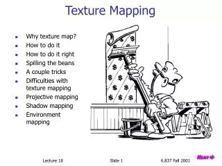
Texture Mapping by Model Pelting and Blending. Deva Ramanan Hao Zhang. Texture mapping. Improve surface appearance Versatile: image map, displacement map, reflection map … Relative small amount of computation. (from Pixar shutterbug image series). Texture mapping (contd.).

E N D
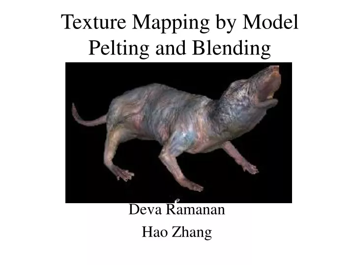
Texture Mapping by Model Pelting and Blending Deva Ramanan Hao Zhang
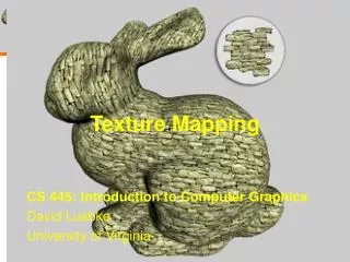
Texture mapping • Improve surface appearance • Versatile: image map, displacement map, reflection map … • Relative small amount of computation (from Pixar shutterbug image series)
Texture mapping (contd.) • Requires “good” parameterization • Minimize distortion • Appears to be seamless
Subdivision surfaces • One single mesh for any topology • Multiple NURBS patches • Maintain smoothness (static and animated) • (u,v)-parameterization • Tensor product B-Spline patches • Shapes of arbitrary topology • Cf. “Character animation” (SS98) (SS98)
Texture mapping on subdivision surfaces • 3D Solid Textures • Multiple local textures • Blend overlapping regions at the seam • Goals (again): • Minimize distortion • Seam blending http://graphics.eecs.wsu.edu/apst/
Texture coordinates • Linear interpolation [Stam98] • texture coords as local (u,v) parameterization • yields C1 interior and C0 cross-boundary • Catmull-Clark on scalar field • position (x,y,z) position+texture (x,y,z,s,t) • subdivide in 5D • yields C2 interior and C1 on extra-ordinary points • needs texture coordinates on M0 (SS98)
Texture mapping analogy: The pelt • Initial control mesh ~ rubber sheet • Stretch mesh to form a pelt • Paint texture on the pelt
Pelting: The Cut • Cut: User specified connected tree of edges
Pelting: Implementation • Approximate rubber sheet by a spring-mass system • Distortion measure: • Elastic energy • Scale invariance
Simulate a spring-mass system • System evolves so as to minimize energy
Blending Texture: Approach -Uo: Pelt Region • Split M0 into 2 overlapping regions: -U1: Patch Region • Use blend functions b0() & b1() along overlapping regions
Example Patch C0 + C1 + C2 + C3= patch region
Review: Domain of Control P A B C D • 2D Cubic B Splines: • Catmull/Clark surfaces: P
Blend Function C0 • Pelt, Patch, and Overlapping Regions surrounding the Cut C1 C2 C3 C4 • b1= cubic B-spline • b0 = 1 - b1
Evaluation • Pelting: • Novel 3D Spring Mass implementation eliminates “buckling” [Maillot et al 93] • Seam blending: • Painted textures • Weaknesses: • Tiled/tesselated pattern • low polygon count meshes
Conclusion • Ultimate goal: • Minimum distortion • texture coordinate control http://www.tfe.umu.se/courses/systemteknik/Multimed2/