Download
1 / 29
290 likes | 400 Vues
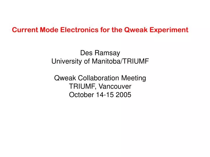
Current Mode Electronics for the Qweak Experiment Des Ramsay University of Manitoba/TRIUMF Qweak Collaboration Meeting TRIUMF, Vancouver October 14-15 2005. Layout of the Qweak Experiment. Synthetic Quartz Scintillator Bars. Shielding Wall. Toroidal Magnet. Liquid Hydrogen Target.

E N D
Current Mode Electronics for the Qweak Experiment Des Ramsay University of Manitoba/TRIUMF Qweak Collaboration Meeting TRIUMF, Vancouver October 14-15 2005
Layout of the Qweak Experiment Synthetic Quartz Scintillator Bars Shielding Wall Toroidal Magnet Liquid Hydrogen Target Front-end electronics in extra shieldingbehind the wall Electron Beam
shot noise: Nature of the Current Mode Signals 50 p.e. per event 50,000 e per event 1 M I-V 800 MHz VME digital signal integrator to DAQ 6.4 A 6.4 V x1000 in shielding outside hall
I-V Preamplifier specs • Gain: Vout/Iin = 1 M with option of up to 10 M. Set by switches on board. • Output: 0 to +10V. Adjustable 2V offset. Drives 130 m RG-213 • Input: 10 A range. (e.g. +1 A to -9 A with +1 V offset.) Tolerates 5m of RG-62 on input. (Noise set primarily by length of input cable.) • Bandwidth: f3db = 30 kHz. (settles to <10-4 in 50 s) • Density: two amplifiers per module (one per detector bar). • Uses 5 V DC Supply. Ground fully isolated by internal DC-DC converter. • BNC connectors. Center conductor negative on input. • Small size for ease of shielding.
MK2 Preamplifier M Chan 1 gain Offset adjust 10 5 2 1 Chan 1 IN Out Chan 2 0.5 1 2.5 5 +5 V DC Chan 2 gain M • Reduced power supply noise • Switchable gains
MK1 -- 1 M gain MK2 -- 225 pf Noise in Vrms Cin (pf) Measured Pspice open 50 24.4 93 70 51.2 179 100 83.0 275 120 112 726 190 182 Gain (M) Noise (Vrms) Channel 1 1 110 2 205 5 470 10 825 Channel 2 5 475 Noise Measurements on Preamps • Noise measured using x200, 50 kHz 5-pole amp, scope 500 kSPS • Noise referred to preamp output. • Used various lengths of RG-58C/U on input – measured capacitance. • Compare to shot noise (for 1 M) : • 70,000 V beam on • 10,000 V LED test • 300 V best-case battery test
Qweak “1 kHz” Integration Scheme next spin state one spin state – (1/250) second 50 s settling time (not to scale) t 1 ms • four 1 ms integrals • target bubbling not seen on few ms time scale • Tsettle should be short to minimize dead time
Existing Gzero Ion Source Signals • signals derived from 20 MHz crystal clock. • Qweak integrator should use this clock as well • Integration triggered by MPS (is present form OK?)
TRIUMF Current Mode VME Integrator • Integration time software selectable 1/300 s to 1/30 s To be set as a fixed number of samples. • Integration triggered by external NIM signal (e.g. MPS) Triggers a selected time after leading edge and runs for pre-set number of samples. • Clocked by 20 MHz NIM signal from ion source. Divided by pre-scale to get sample rate. • Full differential high-impedance input provides common mode noise rejection. • 50 kHz, 5-pole anti-aliasing filter. • 18 bit ADC, 500 ksps. • Four 32-bit sums per integral available to DAQ on VME. No dead time between the four periods. • Buffered output permits reading previous integral during integration. • Eight integrators per single width VME.
VME section details • VME registers • Sample period multiplier, k. Sample period = k*(1/sys_clock) • Number of samples per block, I • Number of sample blocks, m. m = 1, 2, 4. • Gate to Trigger Delay, n. Delay = n*(1/sys_clock). • Gate source, EXT/INT. • System Clock source, EXT/INT. • Block integration time = k*l*(1/sys_clock).Total integration time = k*l*m*(1/sys_clock).(In the FPGA it may be simpler to do 4 sample blocks and a total at all times.) • Data Readout • Sequence number. Shows if a measurement has been lost or skipped. • Block 1-4 sums. 32 bit. • Total sum. 32 bit. • Total number of samples actually taken -- Should equal k*l*m. • Valid data flag or new data ready flag. • Data buffer empty flag, if the data is buffered.
Outstanding Questions • PREAMPS: • What radiation dose will they take? (Dave Mack is testing one) • What gain range should we use on the production amps? (MK2 has 1,2,5,10 and 0.5, 1, 2.5, 5 for evaluation.) • Where, exactly, should we mount them? • INTEGRATORS: • Are we using 1/250 s spin states, and is 50 s settling time reasonable? • Is ion source clock 20 MHz and can we get it as a NIM signal.? • Is MPS good as a trigger and can we get it as a NIM signal?
I … 3 1 2 n t t T = nt Integral From Samples (rectangular rule) • approximate signal with samples • Q = (average I)(T) • band limit signal to small fraction of sampling frequency to eliminate the wiggles and kinks. • we impose an analog cutoff at 1/10 the sampling frequency
Averaging of Digitization Noise • The 18 bit ADCs have ~0.5 LSB rms noise per sample. • This is reduced by averaging ~500 samples per integration. • This will only work if raw signal spreads over enough channels. • Assuming equivalent noise bandwidth 47 kHz (f3db= 30 kHz) and 18 bit ADC at mid range: • condition Q rms noise before channels channels • (e) integration () (FWHM) • beam ON 50,000 69 mV 1420 3339 • LED test 1,000 9.8 mV 201 472 • battery test 1 0.31 mV 6.3 15 • So this is OK even for very quiet signals.
Comparison of Different Noise Sources rms noise on a 1 ms integral Conditionnoise (ppm) beam-ON shot noise 1120 shot noise during LED tests 160 shot noise during battery tests 5 preamplifier noise 2 digital integrator noise 1-2
Changing gains and offset on the TRIUMF MK2 preamp Input side chan 2 chan 1 megohms 5 2.5 1 0.5 1 2 5 10 Output side • Channel 1 is shown set for 1 M and channel 2 for 0.5 M • To change gain move the set switch back towards the input side and move the one you want towards the output side. Note the gains increase away from the center. • The offset is set for 1.0 volts when shipped, but can be changed with the offset pot • To open the preamp for adjustment, remove the hex nuts from the OUTPUT side and remove the black screws from the INPUT side.
Qweak Collaboration Spokespersons Bowman, J. David - Los Alamos National Laboratory Carlini, Roger (Principal Investigator) - Thomas Jefferson National Accelerator Facility Finn, J. Michael - College of William and Mary Kowalski, Stanley - Massachusetts Institute of Technology Page, Shelley - University of Manitoba Qweak Collaboration Members Armstrong, David - College of William and Mary Averett, Todd - College of William and Mary Birchall, James - University of Manitoba Botto, Tancredi - Massachusetts Institute of Technology Bruell, Antje - Thomas Jefferson National Accelerator Facility Chattopadhyay, Swapan - Thomas Jefferson National Accelerator Facility Davis, Charles - TRIUMF Doornbos, J. - TRIUMF Dow, Karen - Massachusetts Institute of Technology Dunne, James - Mississippi State University Ent, Rolf - Thomas Jefferson National Accelerator Facility Erler, Jens - University of Mexico Falk, Willie - University of Manitoba Farkhondeh, Manouchehr - Massachusetts Institute of Technology Forest, Tony - Louisiana Tech University Franklin, Wilbur - Massachusetts Institute of Technology Gaskell, David - Thomas Jefferson National Accelerator Facility Grimm, Klaus - College of William and Mary Hagner, Caren - Virginia Polytechnic Inst. & State Univ. Hersman, F. W. - University of New Hampshire Holtrop, Maurik - University of New Hampshire Johnston, Kathleen - Louisiana Tech University Jones, Richard - University of Connecticut Joo, Kyungseon - University of Connecticut Keppel, Cynthia - Hampton University Khol, Michael - Massachusetts Institute of Technology Korkmaz, Elie - University of Northern British Columbia Lee, Lawrence - TRIUMF Liang, Yongguang - Ohio University Lung, Allison - Thomas Jefferson National Accelerator Facility Mack, David - Thomas Jefferson National Accelerator Facility Majewski, Stanislaw - Thomas Jefferson National Accelerator Mammei, Juliette - Virginia Polytechnic Inst. & State Univ. Mammei, Russell - Virginia Polytechnic Inst. & State Univ. Mitchell, Gregory - Los Alamos National Laboratory Mkrtchyan, Hamlet - Yerevan Physics Institute Morgan, Norman - Virginia Polytechnic Inst. & State Univ. Opper, Allena - Ohio University Penttila, Seppo - Los Alamos National Laboratory Pitt, Mark - Virginia Polytechnic Inst. & State Univ. Poelker, B. (Matt) - Thomas Jefferson National Accelerator Facility Porcelli, Tracy - University of Northern British Columbia Ramsay, William - University of Manitoba Ramsey-Musolf, Michael - California Institute of Technology Roche, Julie - Thomas Jefferson National Accelerator Facility Simicevic, Neven - Louisiana Tech University Smith, Gregory - Thomas Jefferson National Accelerator Facility Smith, Timothy - Dartmouth College Suleiman, Riad - Massachusetts Institute of Technology Taylor, Simon - Massachusetts Institute of Technology Tsentalovich, Evgeni - Massachusetts Institute of Technology van Oers, W.T.H. - University of Manitoba Wells, Steven - Louisiana Tech University Wilburn, W.S. - Los Alamos National Laboratory Wood, Stephen Thomas - Jefferson National Accelerator Facility Zhu, Hongguo - University of New Hampshire Zorn, Carl - Thomas Jefferson National Accelerator Facility Zwart, Townsend - Massachusetts Institute of Technology
Shot Noise equivalent noise bandwidth [Hz] or [A2] one-sided shot noise, charge quantum [C] current [A] • Example, 1 ms integration with beam on, assuming 800 MHz: • Q = 50,000 e • I = 6.4 A (800 MHz x 50,000 e) • B = 500 Hz • in = 7.2 nA rms (7.2 mV with a 1 M preamp) Note that in 1 ms, N = 8 x 10⁵ counts. = 1120 ppm, same as 7.2 nA/6.4 A
Old “120 Hz” Qweak Integration Scheme next spin state one spin state – (1/30) second 200 s settling time (not to scale) t (1/120) • four 1/120 second integrals • multiples of 60 Hz cancel in sum • individual integrals show if 60 Hz (or odd harmonics) was present
current helicity - + - + - + - 6 A 3.6 pA (0.6 ppm p-p) ( ppm) time Size of Qweak Signal • figure shows regular spin flip; in practice use + - - + or - + + - • for 50 kHz noise bandwidth, rms shot noise is 70 nA • on a scope the noise band would be 100,000 x the signal !
+ helicity - helicity counts charge Q0 ADC error +s charge -s Differential Nonlinearity (DNL) Example • ADC reads S channels low below Q0 and jumps to S channels high above Q0 • This causes the measured asymmetry to depart from the real asymmetry, A0, by an amount , where is in channels. • The DNL won’t introduce an asymmetry when none is there, it only changes an existing one.
TRIUMF E761 VME Module DSP serial port (diagnostic) eprom external trigger channel 1 channel 2
Offset Number of samples Sample rate Calibration
TRIUMF Parity 2 module -16-bit ADC - DSP summing - calibration mode - channel offset and gain - takes N samples when triggered - adjustable delay from trigger - delivers gate during integration - features can be programmed


![SUBELEMENT T5 [4 Exam Questions - 4 Groups]](https://cdn0.slideserve.com/1420383/subelement-t5-4-exam-questions-4-groups-dt.jpg)