Download
1 / 39
390 likes | 546 Vues
13: Link Layer, Multiple Access Protocols. Last Modified: 11/7/2014 5:29:18 PM. Goals: understand principles behind data link layer services: sharing a broadcast channel: multiple access link layer addressing error detection, correction

E N D
13: Link Layer, Multiple Access Protocols Last Modified: 11/7/2014 5:29:18 PM 5: DataLink Layer
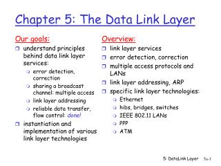
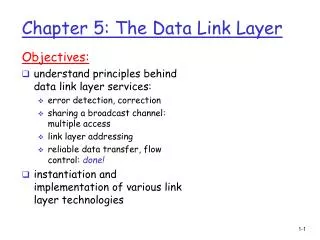
Goals: understand principles behind data link layer services: sharing a broadcast channel: multiple access link layer addressing error detection, correction instantiation and implementation of various link layer technologies Overview: link layer services error detection, correction multiple access protocols and LANs link layer addressing, ARP specific link layer technologies: Ethernet hubs, bridges, switches IEEE 802.11 LANs PPP ATM Data Link Layer 5: DataLink Layer
M H H H H H H H H H t t n n t t n l l M M application transport network link physical M Link Layer: setting the context • two physically connected devices: • host-router, router-router, host-host • unit of data: frame network link physical data link protocol M frame phys. link adapter card 5: DataLink Layer
Link Layer • Node-to-node connectivity • Point-to-point or multiple access • Multiple access requires addressing • Both require rules for sharing the links • Examples: • Point-to-point (single wire, e.g. PPP, SLIP) • Broadcast (shared wire or medium; e.g, Ethernet or wireless) • Switched (e.g., switched Ethernet, ATM etc) 5: DataLink Layer
Communication Technologies • Wired LANs, Wireless LANs (RF or light), Cellular Telephones, Satellites, Packet Radio, Wired Telephone, Voice 5: DataLink Layer
Data Model? • Packet Mode – bursty discrete transmissions • Circuit Mode – continuous traffic 5: DataLink Layer
Basics of Link Layer • Multiple Access Protocols • Error Detection/Correction 5: DataLink Layer
Multiple Access • Multiple Access - fundamental to communication • Two or more communicators use a shared medium to share information • Multiple Access Protocol - Rule for sharing medium to facilitate communication? • Can simultaneous transmissions cause interference? • Claim: humans use multiple access protocols all the time 5: DataLink Layer
Multiple Access protocols • Algorithm that determines how stations share channel, i.e., determine when station can transmit • Note: communication about channel sharing must use channel itself! (or be agreed upon ahead of time) • what to look for in multiple access protocols: • synchronous or asynchronous • information needed about other stations • robustness (e.g., to channel errors) • performance 5: DataLink Layer
MAC Protocols: a taxonomy Three broad classes: • Channel Partitioning • divide channel into smaller “pieces” (time slots, frequency) • allocate piece to node for exclusive use • Random Access • allow collisions • “recover” from collisions • Polling Style • tightly coordinate shared access to avoid collisions Goal: efficient, fair, simple, decentralized 5: DataLink Layer
Channel Partitioning : TDMA TDMA: time division multiple access • access to channel in "rounds" • each station gets fixed length slot (length = pkt trans time) in each round • unused slots go idle • example: 6-station LAN, 1,3,4 have pkt, slots 2,5,6 idle 5: DataLink Layer
Channel Partitioning : FDMA FDMA: frequency division multiple access • channel spectrum divided into frequency bands • each station assigned fixed frequency band • unused transmission time in frequency bands go idle • example: 6-station LAN, 1,3,4 have pkt, frequency bands 2,5,6 idle time frequency bands 5: DataLink Layer
Channel Partitioning: CDMA CDMA (Code Division Multiple Access) • unique “code” assigned to each user; ie, code set partitioning • used mostly in wireless broadcast channels (cellular, satellite,etc) • all users share same frequency, but each user has own “chipping” sequence (ie, code) to encode data • encoded signal = (original data) X (chipping sequence) • For each code there is a spreading factor G • For d bits of user data, G*d bits are trannsmitted • decoding: inner-product of encoded signal and chipping sequence • allows multiple users to “coexist” and transmit simultaneously with minimal interference (if codes are “orthogonal”) 5: DataLink Layer
Can’t Cheat Nature • TDMA – all channel part of time • FDMA – part of channel all the time • CDMA – use all the channel all the time BUT transmit more bits (spread-out) in a specified pattern that avoids interference with others 5: DataLink Layer
TDMA vs FDMA vs CDMA • In TDMA, each station gets the whole channel spectrum some of the time • In FDMA, each station gets part of the channel spectrum all of the time • In CDMA, each station is assigned a code that determines what portions of the channel spectrum they use and for how long to avoid collision with others • All require lots of coordination about who “speaks” when and in what way! • What if didn’t want to coordinate things so tightly? 5: DataLink Layer
Random Access protocols • Random access protocols are alternative to tight coordination • When want to transmit, transmit and hope for the best • If bad things happen, protocol says how to recover 5: DataLink Layer
Random Access Protocols • When node has packet to send • transmit at full channel data rate R. • no a priori coordination among nodes • two or more transmitting nodes -> “collision”, • random access MAC protocol specifies: • how to detect collisions • how to recover from collisions (e.g., via delayed retransmissions) • Examples of random access MAC protocols: • slotted ALOHA • ALOHA • CSMA and CSMA/CD (Ethernet) • Remember Ethernet grew out of technology for broadcast in Hawaiian Islands? 5: DataLink Layer
Random Access: Slotted Aloha • time is divided into equal size slots (= pkt trans. time) • node with new arriving pkt: transmit at beginning of next slot • if collision: retransmit pkt in future slots with probability p, until successful. Success (S), Collision (C), Empty (E) slots 5: DataLink Layer
At best: channel use for useful transmissions 37% of time! Slotted Aloha efficiency Q: what is max fraction slots successful? A: Suppose N stations have packets to send • each transmits in slot with probability p • prob. successful transmission S is: by single node: S= (prob it sends) * (prob all others do not) = p (1-p)(N-1) by any of N nodes S = Prob (only one transmits) = N p (1-p)(N-1) … choosing optimum p as n -> infty ... = 1/e = .37 as N -> infty 5: DataLink Layer
Random Access: Pure (unslotted) ALOHA • unslotted Aloha: simpler, no synchronization • pkt needs transmission: • send without awaiting for beginning of slot • collision probability increases: • pkt sent at t0 collide with other pkts sent in [t0-1, t0+1] 5: DataLink Layer
0.4 0.3 Slotted Aloha protocol constrains effective channel throughput! 0.2 0.1 Pure Aloha 1.5 2.0 0.5 1.0 G = offered load = Np Pure Aloha (cont.) P(success by given node) = P(node transmits) . P(no other node transmits in [p0-1,p0] . P(no other node transmits in [p0-1,p0] = p . (1-p) . (1-p) P(success by any of N nodes) = N p . (1-p) . (1-p) … choosing optimum p as n -> infty ... = 1/(2e) = .18 S = throughput = “goodput” (success rate) 5: DataLink Layer
CSMA: Carrier Sense Multiple Access CSMA: listen before transmit: • If channel sensed idle: transmit entire pkt • If channel sensed busy, defer transmission • Persistent CSMA: retry immediately with probability p when channel becomes idle (may cause instability) • Non-persistent CSMA: retry after random interval • human analogy: don’t interrupt others! 5: DataLink Layer
CSMA collisions spatial layout of nodes along ethernet collisions can occur: propagation delay means two nodes may not year hear each other’s transmission collision: entire packet transmission time wasted note: role of distance and propagation delay in determining collision prob. 5: DataLink Layer
CSMA/CD (Collision Detection) CSMA/CD: carrier sensing, deferral as in CSMA • collisions detected within short time • colliding transmissions aborted, reducing channel wastage • persistent or non-persistent retransmission • collision detection: • easy in wired LANs: measure signal strengths, compare transmitted, received signals • difficult in wireless LANs: receiver shut off while transmitting • human analogy: if start talking at same time some one else does don’t just continue talking 5: DataLink Layer
CSMA/CD collision detection 5: DataLink Layer
Compromise? Polling Style MAC protocols channel partitioning MAC protocols: • share channel efficiently at high load • inefficient at low load: delay in channel access, 1/N bandwidth allocated even if only 1 active node! Random access MAC protocols • efficient at low load: single node can fully utilize channel • high load: collision overhead Polling style protocols (“taking turns”) look for best of both worlds! 5: DataLink Layer
Polling style MAC protocols Token passing: • control token passed from one node to next sequentially. • token message • concerns: • token overhead • latency • single point of failure (token) Polling: • master node “invites” slave nodes to transmit in turn • Request to Send, Clear to Send msgs • concerns: • polling overhead • latency • single point of failure (master) 5: DataLink Layer
Reservation-based protocols Distributed Polling: • time divided into slots • begins with N short reservation slots • reservation slot time equal to channel end-end propagation delay • station with message to send posts reservation • reservation seen by all stations • after reservation slots, message transmissions ordered by known priority 5: DataLink Layer
Summary of MAC protocols • What do you do with a shared media? • Channel Partitioning, by time, frequency or code • Time Division,Code Division, Frequency Division • Random access • ALOHA, S-ALOHA, CSMA, CSMA/CD • carrier sensing: easy in some technologies (wire), hard in others (wireless) • CSMA/CD used in Ethernet • Polling Style • polling from a central cite, token passing 5: DataLink Layer
Basics of Link Layer • Multiple Access Protocols • Error Detection/Correction 5: DataLink Layer
Error Detection • EDC= Error Detection and Correction bits (redundancy) • D = Data protected by error checking, may include header fields • Error detection not 100% reliable! • protocol may miss some errors, but rarely • larger EDC field yields better detection and correction 5: DataLink Layer
Smart Redundancy • In general, more bits of redundancy the stronger the error detection/correction abilities but smart redundancy • What if transmitted another copy of the same thing? • How many bits till not detected? Ability to correct? • Can we do better than that with less space? 5: DataLink Layer
Sender: treat segment contents as sequence of 16-bit integers checksum: addition (1’s complement sum) of segment contents sender puts checksum value into UDP checksum field Receiver: compute checksum of received segment check if computed checksum equals checksum field value Recall: Internet checksum We saw this a bunch of times in upper layers – is this a good choice for the link layer? 5: DataLink Layer
Intelligent choice for link layer? • Tailored to type and frequency of errors expected in the specific technology being used • Some technologies (like fiber) have very low error rates • Some technologies (like wireless) have high error rates • How to we tailor the number of bits to use and *how* we use them to get the desired effect?? 5: DataLink Layer
Single Bit Parity: Detect single bit errors Example: Parity Two Dimensional Bit Parity: Detect and correct single bit errors Want even number of 1’s in each dimension Single Bit vs Two Dimensional Bit Parity: Example of using redundant bits intelligently for increased error detection/correction capability! 0 0 5: DataLink Layer
Beyond parity? • How can we generalize this example of single vs double bit parity? • Is there a theory of using redundant bits efficiently based on the types of errors we expect to find? • Cyclic Redundancy Checks (CRC) views both the data and the redundant bits as binary polynomials and ensures that they satisfy a certain mathematical relationship 5: DataLink Layer
Checksumming: Cyclic Redundancy Check • view data bits, D, as a binary number or binary polynomial • 101011= X^5+X^3+X^1+X^0 = X^5+X^3+X+1. • choose r+1 bit pattern/polynomial (generator), G • goal: choose r CRC bits, R, such that • <D, R> = D* 2r XOR R (shift D over place R in the end) • <D,R> exactly divisible by G (modulo 2) • receiver knows G, divides <D,R> by G. If non-zero remainder: error detected! • can detect all burst errors less than r+1 bits • widely used in practice (ATM, HDCL) 5: DataLink Layer
CRC Example Want: D.2r XOR R = nG equivalently: if we divide D.2r by G, want reminder R D.2r G R = remainder[ ] 5: DataLink Layer
Common CRC Polynomials (G) • CRC-12 used for transmission of streams of 6-bit characters and generates 12-bit FCS • CRC-12: X^12+X^11+X^3+X^2+X+1 • Both CRC-16 and CCRC-CCITT are used for 8 bit transmission streams and both result in 16 bit FCS. Considered to give adequate protection for most applications. • CRC-16: X^16+X^15+X^2+1 (USA) • CRC-CCITT: X^16+X^12+X^5+1 (Europe) • CRC-32 gives extra generates 32 bit FCS. Used by the local network standards committee (IEEE-802) and in some DOD applications. • CRC-32: X^32+X^26+X^23+X^22+X^16+X^12+X^11+X^10+X^8+X^7+X^5+X^4+X^2+X+1 5: DataLink Layer