Download
1 / 12
130 likes | 184 Vues
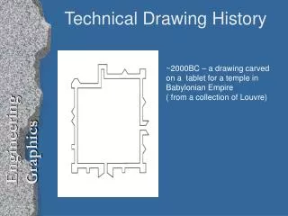
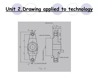
Unit 16: Engineering Drawing for Technicians Third angle projection. Introduction. First or third angle? What is the difference? Who uses them? How can you tell the difference?. Third angle. Sometimes known as ‘American projection’.

E N D
Unit 16: Engineering Drawing for TechniciansThird angle projection
Introduction First or third angle? What is the difference? Who uses them? How can you tell the difference?
Third angle Sometimes known as ‘American projection’. Used in the UK by engineering designers or drawing personnel. The object can be thought of as being ‘drawn on the outside of acardboard box’. Views on drawing can be though of as being in their correctrelative positions.
Showing the four quadrants. The blue arrows indicate the positions from which you would view the objects placed in the first or third quadrants.
Blue object is located in third quadrant and shown partially in dashed lines as hidden detail. The vertical drawing plane is in front of the object and horizontal drawing plane is above the object.
• Object (stepped block) placed in third quadrant. Vertical drawing plane is lower right. Horizontal drawing plane is above the object. • A third drawing plane (extra vertical face) has been added and is shown to the lower left. Notice how each of the three view is projected forward from the object towards the viewer. The object itself is thought of as being a small distance away from each of the drawing planes.
Same view as in previous slide but with the three faces now hatched.
How the ‘box’ can be thought of as being flattened out. Notice the position of the cutting line. The red face is folded upwards and towards the viewer. The blue face is folded sideways and towards the viewer to give the shape shown in the next slide.
• This is what the ‘box’ would look like when flattened out. Notice though, that an extra rectangular area has again been drawn, but this time, at the upper left-hand corner. This is to give our drawing sheet a rectangular profile. • Notice that the view shown on the blue plane is what you would see if you were to view the block in the direction of the left-hand arrow (slide 6). • This is what we meant when we said that the ‘Views on drawing can be though of as being in their correct relative positions’. Likewise, the plan view is above the front face – in its correct relative position.
This slide shows an alternative way of ‘cutting the box’: compare this carefully with slide 8 noting the position of the cutting line.
This is what the ‘box’ would look like when flattened out in a different orientation. Once again, notice that an extra rectangular area has been drawn in but this time at the upper right-hand corner. This would be a more typical layout of a drawing sheet than that shown in slide 8. The choice of layout in reality is governed by selection of the faces of the object that give the most useful detail to the reader of the drawing.
First and third angle projection • A similar representation to the set up shown in slide 4. • The two quadrants have been separated and the object to be drawn removed. • Note: The right-hand representation represents the inside view of a box-like shape viewed from above. • Your brain, however, may trick you into seeing it as the outside of a box viewed from below (an optical illusion) especially of the two bold joining lines are hidden from your view.