Download

1 / 42
790 likes | 2.6k Vues
LINEAR SWEEP VOLTAMMETRY AND CYCLIC VOLTAMMETRY ( LSV & CV). Katalin Neuróhr Research Institute for Solid State Physics and Optics (RISSPO), Hungarian Academy of Sciences. 2 1. 11. 2011. Introduction. LSV voltammetric methode

E N D
LINEAR SWEEP VOLTAMMETRY AND CYCLIC VOLTAMMETRY (LSV & CV) • Katalin Neuróhr Research Institute for Solid State Physics and Optics (RISSPO), Hungarian Academy of Sciences 21. 11. 2011
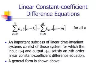
Introduction LSV voltammetric methode the current at the working electrode is measured while the potential between the working electrode and the reference electrode is swept linearly in time ends when it reaches a set potential CV a type of potentiodynamic electrochemical measurement the working electrode potential is ramped linearly versus time like linear sweep voltammetry when cyclic voltammetry reaches a set potential, the potential of the working electrode ramp is inverted the current at the working electrode is plotted versus the applied voltage to give the cyclic voltammogram trace 2
LSV – Nernstian (Reversible) System Fundamentals Consider the reaction We assume here the Erdey-Grúz–Volmer equation and (1) The summary of the kinetics parameters: where l is a dimensionless parameter, if l> 10, the voltammogram is reversible if l< 0.1, the voltammogram is irreversible if 0.1 <l> 10, the voltammogram is quasireversible 3 3
LSV – Nernstian (Reversible) System Solution of the Boundary Value Problem The equations governing this case are (2) (3) (4) The initial condition, (3), merely express the homogeneity of the solution beforethe experiment starts at t = 0, and the semi-infinite condition,(4), is an assertionthat regions distant from theelectrode are unperturbed by the experiment. The third condition,(3),expresses the condition at the electrode surface after thepotential transition,and it embodies the particular experiment we have at hand. 4 4
LSV – Nernstian (Reversible) System Solution of the Boundary Value Problem and the fluxe balance is (5) It is convenient to rewrite (1) (6) Consider reaction, linear diffusion, only species O, with the electrode held initially at Ei potential (7) the potential is swept linearly at v If the rate of electron transfer is rapid at the electrode surface (8) 5 5
LSV – Nernstian (Reversible) System Solution of the Boundary Value Problem after Laplace transformation of (2), the applicationof conditions(3) and (4) yields (9) (10) 6 6
LSV – Nernstian (Reversible) System Solution of the Boundary Value Problem The time dependence is significant because the Laplace transformation of (8) cannot be obtained. The problem was first considered by Randles and Sevcik; the tratement and notation here follow the later work of Nicholson and Shain.The boundary condition (11) Where and and . Laplace transformation of the diffusion equations and application of the initial and semi-infinite conditions leads to [see (9)]: (12) 7 7
LSV – Nernstian (Reversible) System Solution of the Boundary Value Problem After the transform of the current is given by (13) Laplace transformation (14) (15) An initial conditions (t = 0) and two boundary conditions in x. Typically one takes for the initial state: (16) and one uses the semi-infinite limit: (17) 8
LSV – Nernstian (Reversible) System Solution of the Boundary Value Problem Generally: (18) For variable t, we obtain (19) (20) (21) 9 9
LSV – Nernstian (Reversible) System Solution of the Boundary Value Problem The semi-infinite limit can be transformed to (22) hence, B’(s) must be zero for the conditions at hand. Therefore, (23) and (24) Final evolution of and C(x,t) depends on the boundary condition. 10 10
LSV – Nernstian (Reversible) System Solution of the Boundary Value Problem Combining (13) with (12) and inverting, we obtain (25) By letting (26) (25) can be written (27) 11 11
LSV – Nernstian (Reversible) System Solution of the Boundary Value Problem An expression for CR(0,t) can be obtained (assuming R is initially absent): (28) The derivation of (27) and (28) employed only the linear diffusion equations, initial conditions, semi-infinite conditions, and the flux balance. No assumption related to electrode kinetics or technique was made; hence (27) and (28) are general. From these equations and the boundary condition for LSV (11), we obtain (29) (30) where, as before, 12
LSV – Nernstian (Reversible) System Solution of the Boundary Value Problem The solution of this last integral equation would be the function i (t), embodying the desired current/time curve, or since potential is linearly related to time, the current/potential equation. A closed-form solution of (30) cannot be obtained, and a numerical method must be employed. Before solving (30) numerically, it is convenient (a) to change from i(t) to i(E), since that is the way in which the data are usually considered, and (b) to put the equation in a dimensionless form so that a single numerical solution will give results that will be useful under any experimental conditions. This is accomplished by using the following substitution: (31) 13 13
LSV – Nernstian (Reversible) System Solution of the Boundary Value Problem Let . With , so that , ,at and at , we obtain (32) so that (30) can be written (33) Of finally, dividing by , we obtain (34) where (35) 14 14
LSV – Nernstian (Reversible) System Solution of the Boundary Value Problem Note that (34) is the desired equation in terms of the dimensionless variables ,, , and . Thus at any value of, which is a function of E, can be obtained by solution of (34) and, form it, the current can be obtained by rearrangement of (35): (36) • At any given point, is a pure number,so • that (36) gives the functional relationship • betweenthe current at any point on the LSV • curve and the variables.Specifically,i is • proportional toand v1/2.The solution of (34) • has been carried out numerically • (Nicholson and Shain), by a seriessolution • (Sevcik, Reinmuth), analitically in items of • an integral thatmust be evaluted numerically. Fig.1. Linear potentialsweepvoltammogram in terms ofdimensionlesscurrent function. Valueson the potential axis are for 13oC 15 15
LSV – Nernstian (Reversible) System Peak Currentand Potential The function , and hence the current, reaches a maximum where . From (36) the peak current, ip, is (37) At 25oC for in cm2, D0* in cm2/s, CO* mol/cm3, and v in V/s, ip is (38) The peak potential, Ep is mV at 25 oC (39) Difficult to determine The half-peak potential, Ep/2, which is mV at 25oC (40) 16
LSV – Nernstian (Reversible) System Peak Current and Potential Note that E1/2 is located just about midway between Ep and Ep/2, and that a convenient diagnosticfor a nernstian wave is (41) Thuse for a reversible wave, Epis independent of scan rate and ip is proportional to v1/2. The latter property indicates diffusion control and is analogous to the variation of id in chronoamperometry. A convenient in LSV is , which deends on n3/2 and DO1/2. This constant can be used to estimate n for an electrode reaction, if a value of DO can be estimated. 17 17
LSV – Totally Irreversible Systems The Boundary Value Problem For a totally irreversible one-step, one-electron reaction( ) the nerstian boundary condition, (8), is replaced by (42) Where (43) Introducing E(t) from (7) into (43) yields (44) where b = afv and (45) 18 18
LSV – Totally Irreversible Systems The Boundary Value Problem The solution follows in an analogous manner to that described in Totally Reverse Systems and again requires a numerical solution of an integral equation. The current is given by (46) (47) where is a function tabulated from a table. i at any point on the wave varies with vl/2andD0*. For spherical electrodes, values of the spherical correction factor, employed in the equation (48) 19 19
LSV – Totally Irreversible Systems PeakCurrent and Potential The functiongoesthroug a maximum at .Introduction of thisvalueinto (36) yields te followingforthepeakcurrent: (49) Wheretheunitsareasfor (49). From a table, thepeakpotential is givenby mVat 25 oC (50) or (51) (52) 20 20
LSV – Quasireversible Systems Matsuda and Ayabe coined the term quasireverible for raections that show electron transfer kinetic limitations where the reverse reaction has to be considered, and they provided the fisrt treatment of such systems. Fortheone-step, one-electroncase,the corresponding boundary condition is (53) The shape of thepeak and thevariouspeakparameterswereshownto be functions of aand a parameterL, definedas (54) (55) The current is givenby(56) or for 21 21
LSV – Quasireversible Systems whenL > 10, thebehaviorapproachesthat of a reversiblesystem. The values of ip, Eр, and Ep/2depend on L and a. The peak current is given by (57) where ip(rev) is the reversible ip value (37). Note that for a quasireversible reaction, ip is not proportional to v1/2. The peak potential is (58) Forthehalf-peakpotential, wehave(59) 22 22
CV (Experimentalbasis) The basic scheme involves application of a potential sweep to the working electrode. The various parameters of interest are shown in Fig. 2. In linear sweep voltammetry the potential scan is done in only one, stopping at a chosen value, Effor example at t = t1in Fig. 2.The scan direction can be positive or negative and, in principle, thesweep rate can have any value. In cyclic voltammetry, on reaching t = t1 the sweep direction is inverted as shown in Fig. 2 and swept until Emin, then inverted and swept toEmax, etc. Fig.2. Variation of applied potential withtime in cyclic voltammetry, showingtheinitial potential, Ei9 the final potential, f,maximum, Emax, and minimum,Emin,potentials. The sweep rate \dE/dt\ = v.For linear sweep voltammetryconsideronly one segment. The fact that the initial sweep is positive is purely illustrative. 23 23
CV (Experimentalbasis) The importantparametersare • theinitialpotential, Ei • theinitialsweepdirection • thesweeprate, v • the maximum potential, Emax • the minimum potential, Emin • thefinalpotential, Ef It is not common, but can sometimes be convenient, to change the values of Emax and Emin between successive cycles. The total current is (60) 24 24
CV (at planar electrode) For simple electron transfer , with only O initially present in solution. The initial sweep direction is therefore negative. The observed faradaic current depends on the kinetics and transport by diffusion of the electroactive species. It is thus necessary to solve the equations (61) and (62) The boundary conditions are (63 a) (63 b) (63 c) (63 d) 25 25
CV (at planar electrode)– Reversible Systems • The final boundary condition for a reversible system is the Nernst equation • (64) • Solution of the diffusion equations leads to a result in the Laplace domain that cannot be inverted analytically, numerical inversion being necessary. The final result, after inversion, can be expressed in the form(65) • where and (66, 67) • Thus the current is dependent on the square root of the sweep rate. 26 26
CV (at planar electrode)– Reversible Systems • Indicate some quantitative parameters in the curve, which can be deduced from data in table. First, the current function, , passes through a maximum value of 0.4463 at a reduction peak potential Ep,c of(68) • (69) • Secondly, the peak current in amperes is • (70) 27 27
CV (at planar electrode)– Reversible Systems • With A measured in cm2, Doin cm2s-1, [O]oo in mol cm-3 and v in Vs-1, substituting T = 164 К in (65) and (66)—an equation first obtained by Randles and Sevcik. Thirdly, the difference in potential between the potential at half height of the peak, Ep/2,c (I = IP,c/2), and Epcis given by(71) • If the scan direction is inverted after passing the peak for a reduction reaction, then a cyclic voltammogram, as shown schematically in Fig. 3, is obtained. It has been shown that, if the inversion potential, El, is at least 35/n mV after Epc, then • (72) • In which x = 0 for El «Epc and is 3 mV for |Epc - El | = 80/n mV.In this case (73) 28 28
CV (atplanarelectrode)– Reversible Systems • The shape of the anodic curve is always the same, independent of El, but the value of Elalters the position of the anodic curve in relation to the current axis. For this reason Ip,a should be measured from a baseline that is a continuation of the cathodic curve, as shown in Fig. 3. • We can summarize all the information in a diagnostic for linear sweep and cyclic voltammograms of reversible reactions: • Ip v1/2 • Epindependent of v •Ep - Ep/2= 56.6/n mV and for cyclic voltammetry alone •Ep,a – Ep,c = 57.0/n mV •Ip,a/Ip,c =1 Fig.3. Cyclic voltammogram for a reversible system 29 29
CV (atplanarelectrode)– Reversible Systems • As is clear from (65), Ip T-1/2: so, if experiments are conducted attemperatures other than 298 K, thecorrection in Ip is easy to do.Sometimes, and this is one of the disadvantages of conventionalanalysis of cyclicvoltammograms, it is not possible to measure thebaselinewith sufficient precision in order to measure Ipa. However, it is agood approximation to apply the following expression in terms of thepeak current measured from the currentaxis (Ipa)0and the current at theinversion potential (Il)0(see Fig. 1)(74) 30 30
CV (at planar electrode)– Reversible Systems • The capacitive contribution to the total current as given in (60) shouldalso be taken into account. Writing If = Ipcwe have, from (60) and(75) • Substituting typical values (Cd = 20mFcm-2, Do=10-5cm2s-1 and [О]∞ = 10-7 molcm-3 (10-4 M), and n = 1) we obtain • (76) This ratio is 0.1 forv =0.18Vs; if [О]∞ is an order of magnitude higher, i.e. 10-3 M, then the ratio is only 0.01. This shows the advantage of using concentrations as high as possible, millimolar concentrations representing the upper limit. 31 31
CV (at planar electrode)– Irreversible Systems • In the case of an irreversible reaction of the type , linearsweep and cyclic voltammetry lead to the samevoltammetric profile,since no inverse peak appears oninversing the scan direction.To solve (61) and (62), a fifthboundary condition to add to boundaryconditions (63) is (77) • for a reduction, where • (78) • and (79) n' being the number of electrons transferred in the rate-determining step. 32 32
CV (at planar electrode)– Irreversible Systems • As for the reversible case, the mathematical solution in the Laplace domain cannot be inverted analytically. Numerical inversion leads to(80) • and the values of are tabulated, having a maximum of 0.4958 for E = Ep, see a Table. The voltammetric curve is shown in • Fig. 4. The peak current in amperes is(81) Fig.4. Linear sweep voltammogram for an irreversible system.In cyclic voltammetry, on inverting the sweep direction, One obtains only the continuation of current decay 33 33
CV (at planar electrode)– Irreversible Systems • with the units the same as in (70). The peak potential is given by(82) • an alternative expression for Ip is obtained from combining (81) and (82), leading to (83) • From data such as those in a Table it can be deduced that • mV and that mV. With respect to reversible systems the waves are shifted to more negative potentials (reduction), Epdepending on sweep rate. The peaks are broader and lower. 34 34
CV (atplanarelectrode)– Quasi-reversible Systems • For quasi-reversible systems the kinetics of the oxidation andreductionreactions have to be considered simultaneously. Themathematicalsolution is, therefore, more complex, but there arenumerical theoreticalsolutions.As a general conclusion, the extent of irreversibility increases withincrease in sweep rate, while at the same time there is a decrease in thepeak current relative to the reversible case and an increasing separationbetween anodic and cathodic peaks, shown in Fig.5. Fig.5. The effect of increasing irreversibility on the shape of cyclicvoltammograms. 35 35
CV (atplanarelectrode)– Quasi-reversible Systems • Peak shape and associated parameters are conveniently expressed by aparameter, L, which is a quantitative measure of reversibility, beingeffectivelythe ratio kinetics/transport,(84) • When DR = DO = D (85) • showing that small L corresponds to large v (i.e. large s). • The following ranges were suggested for the different types of system at stationary planar electrodes: 36
CV (atplanarelectrode)– Quasi-reversible Systems • The transition between these zones is shown schematically in Fig.6. In the case of cyclic voltammograms and for 0.3 < a < 0.7, Epis almost exclusively dependent on L and hardly varies with a. This can be useful for the calculation of k0using a table, or by interpolation from a working curve drawn using these data. Fig.6. Transition from a reversible to an irreversible system on increasingsweep rate. 37
CV – Adsorbed species • If the reagent or product of an electrode reaction is adsorbed stronglyorweakly on the electrode, the form of the voltammetric wave ismodified.There are two types of situation: • the rate of reaction of adsorbed species is much greater than of species in solution • it is necessary to consider the reactions of both adsorbed species and of those in solution. • For a reversible reaction in which only the adsorbed species О and R contribute to the total current, the current-potential curve for О initially adsorbed and for fast electrode kinetics is given by (86) • where Go,i is the surface concentration of adsorbed O, before the experiment begins, on an electrode of area А, s = (nF/RT)v, boand bRexpress the adsorption energy of О and R respectively, and(87) 38 38
CV – Adsorbed species • The peak current for reduction, Ip,c, is obtained when (bo/bR) = 1, thatis (88) • having the same magnitude for an oxidation. The peak potential is then • (89) The value of Ep is the same for oxidation and for reduction. If the adsorption isotherm is of Langmuir type and(bO/bR) = 1, thenthe voltammetric profile isdescribed by the function (1 + )-2. Fromthis it canbe calculated that the peak width at half height is 90.6/n mV. This is all shown schematically in Fig.7. 39 39 Fig.7. Cyclic voltammogram for a reversible system ofspecies adsorbed on theelectrode.
CV – Spherical electrodes • Considering first potential sweep for a reversible system one obtains (90) • For a reduction, in which r0 is the electrode radius and f(st)a current function different from (st).The peak current is (91) • where ro is in cm and the other units are as in (70) for a planar electrode. Since the spherical correction does not depend on scan rate we can consider spherical electrodes as if they were planar, plus a spherical correction. 40 40
CV – Spherical electrodes • The current function for the spherical correction, f(st),is shown in a table; as can be seen it follows a sigmoidal I-Е profile. For irreversible systems the corresponding expressions are(92) • (93) where r0is in cm and the other units are as in (81) for a planar electrode, the spherical correction being, once more, independent of scan rate. Values of the current function for the spherical correction, f(bt) are given in a table. As for reversible systems, the spherical correction by itself corresponds to a sigmoidal I-Е profile, though of lower slope. 41 41