Download
1 / 29
290 likes | 298 Vues
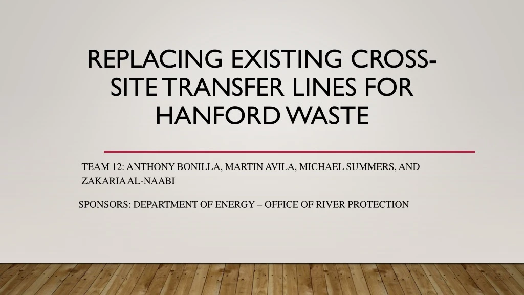
Replacing Existing Cross-Site Transfer Lines for Hanford Waste. team 12: Anthony Bonilla, Martin Avila, Michael Summers, and Zakaria Al-naabi. SPONSORS: DEPARTMENT OF ENERGY – OFFICE OF RIVER PROTECTION. Problem Statement.

E N D
Replacing Existing Cross-Site Transfer Lines for Hanford Waste team 12: Anthony Bonilla, Martin Avila, Michael Summers, and Zakaria Al-naabi SPONSORS: DEPARTMENT OF ENERGY – OFFICE OF RIVER PROTECTION
Problem Statement The Hanford Site located along the Columbia River produced around 56 million gallons of radioactive and chemically hazardous wastes that are stored in underground tanks. The goal is to design a transfer line system that can carry waste from normal 200 West area operations to the treatment, storage, and disposal facilities in the 200 East Area. The cross-site transfer line system has a pipe-in-pipe design and will transfer waste is a slurry form. • Initially design for supernate waste • Recommend what needs to modified to supernate line to support slurry transfer.
Scope The primary piping that will be evaluated for the project is 3-inch, Grade 304L, Schedule 40, stainless steel pipe. The outer pipe, for secondary containment, is 6-inch carbon steel piping that has an epoxy coating to minimize external corrosion. The flowrate through the transfer line is approximately 55 gpm, but can increase up to 140 gpm. The transfer system primary piping shall be designed to withstand a minimum of 400 lbf/ in^2. The transfer system primary piping shall be designed for process fluid temperatures from 80 ºF to 200 ºF and flush water temperatures from 35 ºF to 200 ºF.
Objective • To support the overall mission of the River Protection Project which is to store, treat, and immobilize waste stored in the Hanford Site tanks. • Identify significant risks to the integrity of the RCSTS system once cross-site transfers commence and recommend risk-mitigating solutions to each of them. • Evaluate optimum pipe size to reduce overall project cost.
System Features There are several design features implemented into the RCSTS that enhances the reliability of the overall system. • The pipe-in-pipe configuration of the transfer pipeline is designed to contain liquid and minimize failures in case of a primary leak • Two booster pumps are available at the diversion box, although slurry transfer requires only one. The slurry transfer system currently is not authorized for use • The emergency pump-out connection at the diversion box and the vent station (see Section 2.3) is a backup to the sump pump to ensure the reliability of liquid removal • Two leak detectors are located in each of the diversion box and vent station main buildings, although one in each building is enough to carry out the leak-detection function
Transfer Line Layout Transfer line is segmented into 18 separate sections. Scaled civil drawings were available of each segment. The civil drawings were used to determine the number of bends in the transfer line, providing a rough estimation to the number of fittings and bends within the transfer line. 45° and 90° bends were the most common type of fitting. The frictional losses were estimated and implemented into the total pressure losses calculated for the transfer system .
The lines are buried at nominal depths of 2.5 ft to 4 ft, with minimum depths as shallow as 1.65 ft. (RPP‑18652, Buried Pipe Analysis for DST System Integrity Assessment). Design specifications and construction drawings indicate the transfer lines were installed with a slope toward the receiving tanks to facilitate transfers. Leak detection is being continuously monitored in the annulus space Pipe Design Figure 4. Pipe-in-pipe configuration.
External Pipe Insulation The encasements are composed of various special protective coatings on the 75 active transfer lines. Four primary types of protective features: • Carbon Steel Encasement • Fusion bonded Epoxy coating • Polyurethane foam insulation • HDPE jacket around the foam insulation Figure 5. External Pipe Insulation
Source Tank: 241-SY-102 Tank Waste is sourced from the 241-SY-102 tank found in the SY tank farm in the 200 West Area . The primary tank shell contains the waste and is surrounded by a secondary shell to provide waste containment in the case that the primary shell develops a leak. Supernatant and sludge are both found within the tank. Within the tank there are mixing pumps that allows slurry to be mixed from the supernatant and sludge. • Overall mixture uniformity is currently unknown Tank features an adjustable dipleg to draw out the waste via a pump attached at the top of the tank.
Theory • Pressure drops occur within pipe systems as fluids flow through them. • Friction between the pipe and fluid attributes to the majority of the pressure drops. • Overall frictional loss is dependent on multiple variables: • Length, Inner pipe diameter, fluid velocity, density. • Fluid flow regime can vary depending on the rheological behavior of the fluid. • The friction factor can be found by using the Darcy or the Fanning friction factor model • Moody diagram Figure 7. Moody Diagram.
Theory • During steady state operations, under high flow rate conditions, there is a high enough flow rate so the waste behaves in a Newtonian fashion. • During start-up and shut-down, fluid behaves non-Newtonian like due to low flow rate conditions. • To characterize the fluid we assumed that the fluid viscosity and density are constant. • Length of pipe is fixed at 6 miles and a design flow rate is specified as 140 gal/min. • Reynolds number calculations and an assumed roughness is used to correlate the corresponding friction factors. Table 1.Fluid properties
Theory • Frictional losses stem from skin friction between the fluid and the inner pipe wall and from any fittings and valves within the transfer line. • Various nominal pipe sizes have varying frictional losses associated with them. • Corresponding pumps must be appropriately sized. • Hydraulic power is dependent on volumetric flow rate and overall pressure drop. • Shaft power is the actual required power of the pump. • Takes into account the relative pump efficiency.
Safety is a major concern throughout this operation. Waste is composed of highly radioactive materials and poses serious environmental threats. The waste that is to be transferred from the tanks in the 200 West area to the 200 East area generally consists of Sodium with Hydroxide, Nitrite, Nitrate, and Aluminate as the most dominant ions. Safety Table 2. The supernatant in the system can be chemically
Hazards associated with the chemicals in the waste are considered so the transfer process is as safe as can be • Each chemical possesses hazards that are can be dangerous to the equipment, personel, or environment • Sodium with hydroxide and aluminate can be corrosive to metals • Sodium with nitrite is extremely hazardous to aquatic life • Sodium with aluminate, nitrite, and nitrate are also considered oxidizers • HAZOP Analysis Safety
Table 3. Projected waste transfers. Currently there are a number of transfers scheduled for the following 30+ years. Final Transfer line design needs to be robust enough to last the intended operating lifetime. Total number of transfers will occur sporadically within the coming years. When in operation, individual transfers will occur continuously until the entire transfer is complete. Scheduled Transfers
Calculations • Calculated Reynolds Numbers for various nominal pipe sizes • Determined associated friction factor • Calculated pressure losses due to friction and fittings • Computed pump power requirements Table 4. Design Fluid Properties.
Nominal Pipe Size Comparison Table 5: Nominal pipe size comparison.
Modified Nominal Pipe Size Comparison Table 6. Modified Pump Requirements
Cost Analysis • CAPCOST • Project Cost Estimator • Piping Cost • Vendor Pricing • Pump Cost • Utilities • Number of Pumps • Fittings • Reputable online source • Installation
Results of Economic Analysis • 3.5” Schedule 40 is the most economical • Recommendation is not solely based off economics • Critical Velocity • 3.0” Schedule 40 is the optimal choice Table 7. Overall Cost for piping and pump operation.
Startup : • The Monitor and Control System allows an operator to control and monitor all the processes pertaining to the cross-site transfers. • The operator receives an authorization signal from the connected instrumentation after pre-startup operations. • After receiving the authorization signal, the operators are permitted to turn on the pumps and initiate the transfer. • Shutdown : • Shutdown operations includes: the flushing operation and the draining operation. Startup/Shut Down
Recommendations Results from the project point towards the same design as the existing RCSTS transfer line • The sizing of the inner and outer pipes should stay the same • Piping materials should also stay the same (304L Schedule 40 Stainless steel) • Exception would be the containment jacket around the insulation foam • Fiberglass-reinforced plastic over High-density polyethylene jackets We recommend that a robust integrity evaluation of the current transfer system be performed to determine if the system is operational. • Using current line would result in saving money and possibly time
Future Work Focus on a better alternative for the leak detection system • Internally based leak-detection system • Acoustic pressure wave system • Externally based leak-detection system • Acoustic emission detectors • Fiber-optic leak detection • Infrared radiometric pipeline testing
References 1. Chhabra, R.P. “Non-Newtonian Fluids: An Introduction.” Accessed February 6, 2019. http://www.physics.iitm.ac.in/~compflu/Lect-notes/chhabra.pdf. 2. Delplace, F., Leuliet, J.C. “Generalized Reynolds number for the Flow of Power Law Fluids in Cylindrical Ducts of Arbitrary Cross-Section.” The Chemical EngineeringJournaland the BiochemicalEngineering Journal. January 1995. Accessed February 6, 2019. https://www.sciencedirect.com/science/article/pii/0923046794028496. 3. Kudela, Henryk. “Hydraulic Losses in Pipes.” Accessed February 13, 2019. http://fluid.itcmp.pwr.wroc.pl/~znmp/dydaktyka/fundam_FM/Lecture11_12.pdf. 4. Majeed, Jafar G. “Non-Newtonian Fluid.” Accessed February 13, 2019. https://uomustansiriyah.edu.iq/media/lectures/5/5_2016_04_18!11_29_01_AM.pdf. 5. “Non-Newtonian Fluids.” January 2014. Accessed February 6, 2019. http://www.cchem.berkeley.edu/cbe150a/mom/nonewt.ppt. 6. “Pipe Pressure Drop Calculations.” Pipe Flow. Accessed February 13, 2019. https://www.pipeflow.com/pipe-pressure-drop-calculations. 7. “Pressure Drop in Pipes.” Engineers Edge. Accessed February 6, 2019. https://www.engineersedge.com/fluid_flow/pressure_drop/pressure_drop.htm. 8. “Pressure Loss in Pipe.” Neutrium. April 29, 2012. Accessed February 6, 2019. https://neutrium.net/fluid_flow/pressure-loss-in-pipe. 9. “Stainless Steel Pipe.” MetalsDepot. Accessed February 23, 2019.https://www.metalsdepot.com/stainless-steel-products/stainless-steel-pipe 10. McCabe, W. L., Smith, J. C. & Harriott, P. (2005). Unit Operations of Chemical Engineering (7th ed.). New York, NY: McGraw-Hill 11. Antaki, G., Cole, J., & Scribner, T. Tank Farms Waste Transfer System Fitness-for-Service Requirements and Recommendations. Richland, WA: Washington River Protection Solutions. 12. Blaak, T. M. (2013). System Design Description for the Replacement Cross-Site Transfer System Between 200 West and 200 East Tank Farms. Richland, WA: Washington River Protection Solutions.
References 13. “Carbon Steel Piping Advantages.” Florida Pipe Steel RSS. Accessed April 9, 2019. www.steel4sale.com/carbon-steel-piping-advantages/ 14. Richard Turton. Analysis, Synthesis, and Design of Chemical Processes. 5th ed., 2013. 15. Riffe, D J. “Hanford Site Hazards Guide.” Hanford, Jan. 2019. Accessed April 10, 2019. www.hanford.gov/files.cfm/HNF-56110_Hanford_Site_Hazards_Guide.pdf 16. “Polyurethanes.” Polyurethane Products and Benefits. Accessed April 10, 2019. www.polyurethane.americanchemistry.com/Polyurethane-Products-and-Benefits/ 17. “FRP versus HDPE.” Industrial Plastic Systems, Inc, 2005. Accessed April 9, 2019. www.ips-frp.com/wp-content/uploads/2014/11/HDPE-Versus-FRP.pdf 18. “Sodium Hydroxide SDS.” Sigma-Aldrich, 28 Sept. 2017. Accessed March 7, 2019. www.sigmaaldrich.com/MSDS/MSDS/DisplayMSDSPage.do?country=US&language=en&productNumber=S8263&brand=SIGALD&PageToGoToURL=https%3A%2F%2Fwww.sigmaaldrich.com%2Fcatalog%2Fproduct%2Fsigald%2Fs8263%3Flang%3Den. 19. Anderson, Stephen A. “Out of Sight, Out of Mind?” Hydrocarbon Engineering, Aug. 2010. Accessed February 22, 2019.www.intertek.com/articles/2010-08-corrosion-under-insulation/. 20. Foray, Jeff. “Energy Efficiency Considerations in Pump and Pump Stations.” 14 Mar. 2014. Accessed March 24, 2019.www.energy.wsu.edu/LinkClick.aspx?fileticket=t3ubiA8D8A4%3D&tabid=692&mid=1345. 21. “Waveguard LDS.” Pipeline Technologies and Services, 2014,www.pipetechs.com/?page_id=111. 22. Athanasios, Anastasopoulos. “Leak Detection Using Acoustic Emission.” Acoustic Emission Leak Detection of Liquid Filled Buried Pipeline. 2009. pdfs.semanticscholar.org/7ae4/7e4ae26e2699b22c3df3119014718e11da5.pdf. 23. Fu, Qiang. “Pipeline Leak Detection Based on Fiber Optic Early-Warning System.” doi:10.1016/j.proeng.2010.11.013.