Download

1 / 27
280 likes | 456 Vues
Chapter 3 Supplementary Components and Systems. “Introduction to Modern Power Electronics”, 2 nd Ed., John Wiley 2010 by Andrzej M. Trzynadlowski. Driver for an SCR with transformer isolation. Fig. 3.1. Optically isolated driver for an SCR. Fig. 3.2. Non-isolated driver for a triac.

E N D
Chapter 3Supplementary Components and Systems “Introduction to Modern Power Electronics”, 2nd Ed., John Wiley 2010 by Andrzej M. Trzynadlowski
Driver for an SCR with transformer isolation Fig. 3.1 Chapter 3
Optically isolated driver for an SCR Fig. 3.2 Chapter 3
Non-isolated driver for a triac Fig. 3.3 Chapter 3
Optically isolated driver for a triac Fig. 3.4 Chapter 3
Driver for a GTO with transformer isolation Fig. 3.5 Chapter 3
Non-isolated drivers for a BJT: (a) single-transistor driver, (b) driver with a class B output stage Fig. 3.6 Chapter 3
Antisaturation Baker’s clamp for a BJT Fig. 3.7 Chapter 3
Driver for a BJT with transformer isolation Fig. 3.8 Chapter 3
Driver for a BJT with transformer isolation Fig. 3.9 Chapter 3
Gate drive for a power MOSFET with a high-current TTL clock driver Fig. 3.10 Chapter 3
Driver for a power MOSFET with transformer isolation Fig. 3.11 Chapter 3
Driver for a power MOSFET with optical isolation Fig. 3.12 Chapter 3
SCR crowbar for overcurrent protection of a power electronic converter Fig. 3.13 Chapter 3
Totem-pole arrangement of two switches in a leg of a bridge topology Fig. 3.14 Chapter 3
BJT-based chopper with an RC snubber: (a) circuit diagram, (b) equivalent circuit in the off state Fig. 3.15 Chapter 3
Voltage and current waveforms in the chopper of Fig. 3.15: (a) without snubber, (b) with snubber Fig. 3.16 Chapter 3
Switching trajectories of the BJT of Fig. 3.15: chopper iof Fig. 3.15: (a) without snubber, (b) with snubber Fig. 3.17 Chapter 3
Snubbers for: (a) power diode, (b) SCR Fig. 3.18 Chapter 3
GTO with turn-on and turn-off snubbers Fig. 3.19 Chapter 3
Combined on-and-off snubber for a transistor Fig. 3.20 Chapter 3
Snubber for transistors in bridge converters: (a) RC, (b) RCD, (c) charge and discharge RCD, (d) discharge-suppressing RCD Fig. 3.21 Chapter 3
Turn-off capacitive snubber with passive energy recovery Fig. 3.22 Chapter 3
Turn-off capacitive snubber for a GTO with active energy recovery Fig 3.23 Chapter 3
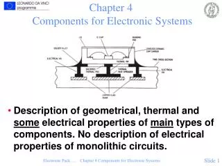
Power diode with a heat sink: (a) physical arrangement, (b) thermal equivalent circuit Fig. 3.24 Chapter 3
Block diagram of an adjustable-speed ac drive Fig. 3.25 Chapter 3