Download
1 / 31
310 likes | 390 Vues
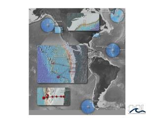
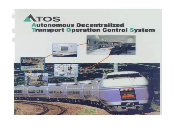
Tokyo-metropolitan area. Yamanote-line. Chuo-line. scale. Joubann-line. Toukaido-line. 14 lines, 300 stations 1200km length 6200 trains/day 16Millon Passengers / day. Oomiya. computers. tabata. 300 minicomputers 1600 WS, PC 200 controllers. Ueno. Hachiouji. Shinjuku.

E N D
Tokyo-metropolitan area Yamanote-line Chuo-line scale Joubann-line Toukaido-line 14 lines, 300 stations 1200km length 6200 trains/day 16Millon Passengers / day Oomiya computers tabata 300 minicomputers 1600 WS, PC 200 controllers Ueno Hachiouji Shinjuku Nishifunabashi Tokyo Chiba Shinagawa objectives safety/punctuality efficient resources utilization Yokohama travel/emergent information services Tokyo-Metropolitan Train-Traffic Control/Information System
system control information structure global-area network maintenance ws ws scheduling G G control data information data G G control-Ethernet information-Ethernet local-area network traffic control filtering information service controller filtering control-Ethernet information-Ethernet station controller ws station controller information terminal pc station controller I/O I/O functions ・ train tracking ・ route control ・ traffic control ・ maintenance / test ・ scheduling ・ planning of maintenance ・ information services to passengers Heterogeneous System
Successive construction Successive construction is also called Step-by-step construction Aims Step-by-step construction 1. Risk reduction to increase reliability 2. Early construction to shorten period <Restricted condition> 3. Completion within mission time 4. Non-stop system change 1. To input functions online gradually by step-by-step way after Online test to ascertain functions 2. Online test; a. Online monitoring run test b. Online test using real data
1. Introduction Background (1)User Needs; Recent large system has the feature of growing system; a. Heterogeneous needs ( Control, Information service) b. Long construction period of system c. How to meet changing needs ( Flexibility, Non-stop change) (2)Problems of growing system; System growing has a major risk to loose system reliability Technical Issues (1)High-Assurance System is To make growing system to keep reliability and stable operation To minimize the risk to loose reliability through growing phase (2)Assurance Technology is The Technology achieving High-Assurance System
Online Input Online input test Sdm Sd2 Test Sd1 Online function Mission time Tm Un-operated function Sd1 Sd2 Sdm Function Volume Sd1 Sd2 Sd1 Time Subsystem set Sd |Sd|=M Sd1 Sdm Sd2 2. Step-by-step construction • <System construction way> • Subsystem set(Sdi) input to online by step-by-step way • 2. To ensure reliability by online test* before online input • *online test; testing in as equivalent environment as online • 3. Completion within mission time Step-by-step construction
3. Evaluation index for system construction(1) To ensure reliability Functional reliability Early construction × = To increase Functional achievement To test to increase reliability in online equivalent environment 1. Adoption of Functional reliability a. Functional Achievement = Online available functions / total functions b. Functional reliability( Rt) = Functional Achievement ・Reliability
3.1 Evaluation index for system construction(2) <Definition of Functional reliability> 1.Functional reliability(Rt)=Functional achievement( ) Reliability(P) <Definition of Average functional reliability> 2. Average functional reliability (Af) Function F to be achieved by subsystem S under X is defined as the sum of functions to be owned by each subsystem Functional achievement ψ is online available function f divided by total function F. Functional achievement in state X Functional reliability Rt is defined Functional achievement times expected reliability P. The value, which is the integral value of functional reliability from 0 to mission time Tm, divided by mission time Tm. Tm; Mission time (system buildup time) Rt(Xt) : functional reliability in system state Xt at time t
3.2 Definition of assurance evaluation Functional reliability(Rt) Tm The best solution is to make the area maximum Rt(XtM) Construction time(Test time) of Sd1 TT(|SdM|,|XtM-1|) TT(|Sdi|,|Xt1|) Rt(Xti) TT(|Sd1|,|Xt0|) Rt(Xt1) Online start (t=0) Time(t) SdM start operation Sdi start operation Sd1 start operation We use Average functional reliability as the evaluation index of assurance for system construction to compromise early construction and reliability within mission time. Assurance performance is described as follows. Tm; system buildup time( Mission time) Rt(Xt) : functional reliability in system state Xt at time t
CC CC TF(0) TF(1) Data Data Data Field(DF) Online Data Test Data BIT BIT BIT ACP ACP ACP Atom EXT APL APL Output Suppression Test Mode Online Operation BIT:Built In Tester EXT:External Tester 4. Step-by-step autonomous construction technique 4.1 System architecture and online test(1) Online Test using Online Data
CC TF(1) Data Data Field(DF) TF(0) CC Data Online Data Test Data BIT BIT BIT ACP ACP ACP Atom EXT APL APL Online Operation Output Suppression Test Mode 4.2 System architecture and online test(2) Online Test during Online Operation
4.3 Actual online input sequence on ADS (1) The model of ADS Data format Data field (DF) CCi Data CC1 CCi; Content code CC2 CC3 ADS; Event driven system by using Content code. CC1 CC3 CC2 CC1 …… S1 S2 S3 S4 S8 S4 Process flow CC2 (1)Process flows from upstream to downstream on ADS. (not symmetrical structure) (2)System generally consists of heterogeneous functions such as control and information service. (not homogeneous functions) CC2 S5 S2 CC1 Common Control S6 S1 CC2 CC3 CC1 S7 S3 CC3 Information service S8 Si; subsystem
4.4 Decision factors for online input sequence and technique Factors Technique • Function volume; • We define that it depends on • subsystems relations. • Because many problems on • construction are caused by • subsystems relations. • Basic function volume • is decided by the number • of input messages • On ADS input message is • content code • Input message (2) Basic function volume S4 CC2 1 CC2 CC2 S5 CC2 S2 1 CC1 1 CC1 S6 CC2 1 CC2 Si; subsystem ; input message( content code) CCi
S4 CC2 X CC2 S5 S2 CC1 S6 CC2 4.5 Decision factors for online input sequence and technique Factors Technique 2. Impact area of subsystem stop by any failure 2. To define impact rating by impact area to be stopped <Case of S2 stop> >>S2,S4,S5, S6 become stop < Impact rating> 1 CC2 CC2 1 4 CC1 1 CC2 Impact rating S2 =(1+3)=4 Si; subsystem
4.6 Decision factors for online input sequence and technique Factors Technique 3. Co-existence of heterogeneous application 3. To decide application impact rating by application property S4 CC2 Ex. Application impact rating; Common>Control >Information service (This is different on each system situation) CC2 S5 S2 CC1 Common Control S6 S1 CC2 CC3 CC1 S7 S3 CC3 Information service S8 Si; subsystem
4.7 Comparison of construction sequence(1) Simulation model Simulation result S3 1 api= 1.0 Mission time Tm S4 S2 1 4 S5 1 S1 8 api= 0.5 S7 0.5 S6 1.5 S8 0.5 api; Application indicator <Condition> Required reliability Rs=1 ST=10 One-way architecture <Construction pattern> Case1; 1,(2,6),(3,4,5,7,8) Case2; 1,(2,3,4,5),(6,7,8) Case3; (1-8) Lump sum Case4; (1,2,3,4,5,6,7,8) one-by-one Case5;(1,2),(3,4),(5,6),(7,8) 1. Assurance performance Af a. The highest Af is 0.79 on case 2 b. The followed order case 5,1,4,3 2. Construction sequence according to Assurance performance Af is effective
4.8 Comparison of construction sequence(2) Case1 Item Case2 1 1 CC2 CC2 2nd step CC2 CC2 1 1 4 4 CC1 CC1 Control Control 1 1 Case 8 CC2 CC2 8 1st step CC3 CC3 CC1 CC1 1st step 0.5 0.5 1.5 1.5 CC3 CC3 3rd step 0.5 0.5 2nd step Information service Information service 3rd step Input I/F Output I/F Tpi Input I/F Output I/F Tpi 2 8 1 8 2 1 1st step 3 7 2 1 5 5.5 2nd step 2 2.5 5 4 5 1 3rd step Af =0.79 Af =0.74 Af
5. Conclusions • Assurance performance Af as the evaluation index for the system construction in which heterogeneous application coexist. • Successive construction technology, which build up the system by step-by-step way, that decides system construction sequence to maximize the assurance performance. • Successive construction technology is very effective by the simulation results and the case study.
Fig. 10 Photo of the on-board integrated system Degital-ATC
Outline 1.Functions of the Automatic Train Control (ATC) System 2.How to replace old ATC with new ATC 3.System Modeling 4.Modeling of System Replacement 5.Method of Assurance Evaluation 6.Evaluation (Quantitative Comparison) 7.Total Assurance Definition 8.Conclusion
Test Sequence Test 営業運転中 operation Test 営業運転中 Step-by-step test and operation operation Test Test 営業運転中 operation Test Test Test 営業運転中 operation Test Test Test 営業運転中
Current ATC system speed 90km/h Permitted speed Actual train speed 65km/h 3. Compare speeds 45km/h 4. Output brakes 90 65 65 45 0 1. Train detection 2. Permitted speed information signal Ground equipment
Effective /Test Stop Position CC ・ ・ ・ D-ATC system 4. Pattern generation Braking pattern Actual train speed 3. Locating position Stop position Communication equipment Communication equipment Ground Equipment (ATC logic device) 2. Transmit 1. Train detection
Effective /Test Stop Position CC ・ ・ ・ Future ATC system 5. Pattern generation Braking pattern Actual train speed 4. Locating position 1. Locating position Position data 2. Transmit 3. Transmit Ground Equipment
Methods of on-board system 90 65 65 45 0 Old ATC signal New ATC signal Test data cc Effective /Test Stop position
Modeling of ATC system Current ATC The definition of function: 1. Sc detects the train. 2. Sc generates and transmits the permitted speed information. 3. Ticontrols the brakes according to the permitted speed information T1 T2 T3 Tn … Data field Data; Speed V Permitted Speed Sc D-ATC T1 T2 T3 Tn The definition of function: 1. SD detects the position of train Ti. 2. SD creates Dsi-1 according to Ti and transmits it. 3. Ti-1 is controlled according to Dsi-1. … Data field Data ; Stop Position SD Effective /Test Stop Position CC ・ ・ ・
Modeling of ATC system Future ATC T1 T2 T3 Tn The definition of function: 1. Ti recognizes the own position and transmits it. 2. SF creates Dsi-1 according to Ti and transmits it. 3. Ti-1 is controlled according to Dsi-1 … Data field SF Effective /Test Stop Position CC ・ ・ ・ Effective /Test Stop Position CC ・ ・ ・
… T1 T2 T3 Tn So So Sn Sn Configuration of on-board system On-board system On-board integrated system type DataField On-board integrated system can read both data fields of the new ATC and the old ATC. Old ATC New ATC … TN1 TN2 TNk … TO1 TO2 TOm On-board discrete system type DataField GW On-board discrete system can only read the new ATC data field. Therefore the new ATC data field is connected to the old ATC data field via gateway (GW) GW converts the old ATC information into the new ATC information.
So So S S S o o o So Modeling of system replacement 1 1 T T Tc Tc T T ... j-1 1 1 2 3 N ... Tc Tc ... Tc 2 j N Data Field Data Field 2 2 T T Tc Tc T T ... j-1 1 1 2 i N ... Tc Tn ... Tc 2 j N GW Old ATC Old ATC S S N N Coexistence period Coexistence period 3 3 Tn Tn T T T T ... j-1 1 1 2 i N ... Tn Tn ... Tc 2 j N N GW New ATC New ATC S S N N Tn Tn 4 4 j-1 1 T T T T ... ... Tn Tn ... Tn 1 2 i N 2 j N Data Field Data Field S S N N • Replacement using On-board • Discrete system • Replacement using On-board • Integrated System
Conclusions • Train control system models and system replacement models were created. • Testing Assurance evaluation method. • Total Testing Assurance. • Evaluation at our train control system. • On-board integrated system is more effective and adaptable to practical use.
Conclusions • ADS : Control system Information system • Research : world-wide • ①The 1st ISADS 1993 The 7th ISADS 2003 • ② IBM : Autonomous Computing (2001) • 21st Century Strategic Research Initiative • (websphere / DB2 / Tivoli / Lotus)