Download
1 / 33
330 likes | 458 Vues
CN2668 Routers and Switches (V2). Kemtis Kunanuraksapong MSIS with Distinction MCTS, MCDST, MCP, A+. Agenda. Chapter 13: Advanced Switching Concepts Exercise Quiz. Spanning Tree Protocol. Physical path loops

E N D
CN2668Routers and Switches (V2) Kemtis Kunanuraksapong MSIS with Distinction MCTS, MCDST, MCP, A+
Agenda • Chapter 13: Advanced Switching Concepts • Exercise • Quiz
Spanning Tree Protocol • Physical path loops • A physical connection created when connected with two or more physical media links • Help improve a network’s fault tolerance • Drawback • Can result in endless packet looping • See Figure 13-1 on Page 366 • Spanning Tree Protocol (STP) • A layer 2 link management protocol designed to prevent looping on bridges and switches • The specification for STP is IEEE 802.1d
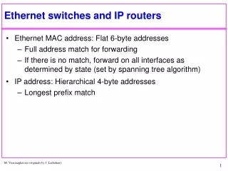
Spanning Tree Protocol (continued) • Spanning Tree Algorithm (STA) • To interrupt the logical loop created by a physical loop in a bridged/switched environment • Some or certain ports on are configured to discard the frames • Building a logical path • Switches and bridges on a network use an election process to configure a single logical path • A root bridge (root device) is selected • Then, the other switches and bridges configure their ports, using the root bridge as a point of reference • The decision based on the lowest number of priority or lowest MAC address if both have same priority number
Spanning Tree Protocol (continued) • Bridges use STP to transfer the information about each bridge’s MAC address and priority number • Bridge protocol data units (BPDU) or Configuration bridge protocol data units (CBPDU) • The messages the devices send to one another • Each bridge or switch determines which of its own ports offers the best path to the root bridge • Root ports • The BPDU messages are sent between the root bridge and the best ports on the other devices
Spanning Tree Protocol (continued) • If BPDUs are not received for a certain period of time • The non-root-bridge devices will assume that the root bridge has failed, and a new root bridge will be elected • Once the root bridge is determined and the switches and bridges have calculated their paths to the root bridge • The logical loop is removed by one of the switches or bridges
Spanning Tree Protocol (continued) • Port states • STP will cause the ports on a switch or bridge to settle into a stable state • Stable states • The normal operating states of ports • Transitory states • Prevent logical loops during a period of transition from one root bridge to another while a new root bridge is being elected
Spanning Tree Protocol (continued) • The stable states are as follows: • Blocking • Send and receive STP messages, not the data frames • Forwarding • Receive and send all data frames, STP messages, and learn new MAC address • Disabled • The transitory states are as follows: • Listening • Learning
Spanning Tree Protocol (continued) • Ports on STP-enabled devices move through the different states as indicated in the following list: • From bridge/switch bootup to blocking • From blocking to listening (or to disabled) • From listening to learning (or to disabled) • From learning to forwarding (or to disabled) • From forwarding to disabled
Spanning Tree Protocol (continued) • Topology changes • When the topology is changed, STP-enabled devices react automatically • If CBPDUs are not received, Device will claim to be the root bridge and continue the path build process • Per-VLAN STP (PVSTP) • Operates on VLANs and treats all VLANs connected as separate physical networks
Spanning Tree Protocol (continued) • Spanning Tree PortFast • Allows you to configure a switch to bypass some of the latency (delay) • Only if that device will not create the loop • Configuring STP • See Table 13-1 on Page 369 • Rapid STP (RSTP) • Use IEEE 802.1w
Virtual LANs • A grouping of network devices that is not restricted to a physical segment or switch • Can be configured on most switches to restructure broadcast domains • Broadcast domain • Group of network devices that will receive LAN broadcast traffic from each other
Virtual LANs (continued) • Management VLAN (also known as the default VLAN) • By default, every port on a switch is in VLAN 1 • You can create multiple VLANs on a single switch • Or create one VLAN across multiple switches • A VLAN is a layer 2 implementation, and does not affect layer 3 logical addressing • See Figure 13-2 and 13-3 on Page 371
Benefits of VLANs • Benefits: • Ease of adding and moving stations on the LAN • Ease of reconfiguring the LAN • Better traffic control • Because the administrator can set the size of the broadcast domain • Increased security • VLANs can be configured by network administrators to allow membership only for certain devices • See Figure 13-4 on Page 373
Dynamic vs. Static VLANs • Static VLANs • Configured port-by-port • The network administrator manually types in the mapping for each port and VLAN • Dynamic VLAN • Uses a software database of MAC address-to-VLAN mappings that is created manually • Ports can automatically determine their VLAN configuration
VLAN Standardization • Frame filtering • One table for each VLAN • Master table that was shared by all VLANs • Frame tagging • Also known as frame identification • IEEE 802.1q specification
VLAN Standardization (continued) • Frame tagging • Involves adding a four-byte field to the actual Ethernet frame to identify the VLAN and other pertinent information • Makes it easier and more efficient to ship VLAN frames across network backbones • Switches on the other side of the backbone can simply read the frame instead of being required to refer back to a frame-filtering table • Inter-Switch Link (ISL) protocol • Cisco-based that supports only
Creating VLANs • To use the config-vlan mode, you type the following: • Rm410HL(config)#VLAN 2 • Rm410HL(config-vlan)name production • To use the VLAN configuration mode, you start by entering the VLAN database • Rm410HL #VLAN database • Rm410HL(vlan)#vlan 2 name production
Creating VLANs (continued) • To assign switch ports to the new VLANs • Ports can be assigned as static or dynamic • Rm410HL(config)#int f0/5 • Rm410HL(config-if)#switchport access vlan 2 • To remove a VLAN, use the no parameter: • Rm410HL(config)#no vlan 2
Link Types and Configuration • Trunk links • Switch-to- switch or switch-to-router links that can carry traffic from multiple VLANs • Access links • Links to non-VLAN-aware devices such as hubs and individual workstations
Link Types and Configuration (continued) • 5 different states for a trunk link: • Auto – if connected device is set to on or desireable • Desirable – if connected device is set to on or desireable, or auto • Nonegotiate – will not negotiate that status with any other device • Off – is not a trunk interface and will try to disable • On – is not a trunk interface and will try to disable
Link Types and Configuration (continued) • To configure a trunk link on a Catalyst 2950 • Rm401HL# Conf t • Rm401HL(config)# intfastethernet 0/24 • Rm401HL(config-if)# switchport mode trunk • You can prevent ports from using VLAN • Rm401HL# Conf t • Rm401HL(config)# intfastethernet 0/24 • Rm401HL(config-if)# switchport trunk allowed vlan remove 4
Link Types and Configuration (continued) • Switch interface descriptions • You can configure a name for each port on a switch • Rm401HL# Conf t • Rm401HL(config)# int f0/1 • Rm401HL(config-if)# description productionVlan • Rm401HL(config-if)# int f0/24 • Rm401HL(config-if)# description trunkbldg777
VLAN Trunking Protocol • To manage all of the configured VLANs that traverse trunks between switches • A layer 2 messaging protocol • VTP domains • VTP devices are organized into domains • Each switch can only be in one VTP domain at a time • All devices that need to share information must be in the same VTP domain • Rm410HL#vlan database • Rm410HL(vlan)#vtp domain domainname
VTP Device Modes • Server • Device can add, rename, and delete VLANs and propagate those changes to the rest of the VTP devices • Client • Device is not allowed to make changes to the VLAN structure, but it can receive, interpret, and propagate changes made by a server • Transparent • A device is not participating in VTP communications, other than to forward that information through its configured trunk links
VLAN Trunking Protocol (continued) • VTP pruning option • Reduces the number of VTP updates that traverse a link • Off by default on all switches • If you turn VTP pruning on • VTP message broadcasts are only sent through trunk links that must have the information • VLAN 1 is not eligible to be pruned because it is an administrative (and default) VLAN
Nonswitching Hubs and VLANs • Important considerations: • All the systems attached to the hub will be in the same VLAN • You will have to physically attach the device to another hub or switch port to change its VLAN assignment, if you move the device
Routers and VLANs • To increase security • Must be used to manage traffic between different VLANs • Implement access lists • Increase inter-VLAN security • A router allows restrictions to be placed on station addresses, application types, and protocol types
Routers and VLANs (continued) • The router will accept the frame tagged by the sending VLAN and determine the best path to the destination address • The router will then switch the packet to the appropriate interface and forward it to the destination address
CCNA Guide to Cisco Networking Fundamentals, Fourth Edition Routers and VLANs (continued) • Router-on-a-stick • If a single link is used to connect an external router with the switch containing multiple VLANs • Trunking is required for inter-VLAN routing • Trunking is the process of using either ISL or 802.1q to allow multiple VLAN traffic on the same link • For instance, an ISL trunk link would encapsulate each packet with the associated VLAN information and allow the router to route the packet accordingly
Assignment • Review Questions • 1 – 25 • Exercise
Exercise • Place 2 switches and 2 workstation, do not connect the cables • On first switch rename it to server (for easier understanding) • Create VLAN as shown on Page 374-375 • Set the VTP domain • Server#vlan database • Server (vlan)#VTP domain RM403 • Create the trunk link on Server. See page 376.
Exercise • On second switch rename it to client (for easier understanding) • Connect UTP cable from WS1 to port 5 • Connect cross-over cable to port 24 on Server and Client • Type the following on Client switches • Enable • Show vlan