Download
1 / 26
260 likes | 267 Vues
Bunched-Beam Phase Rotation for a Neutrino Factory. David Neuffer, Andreas Van Ginneken, Daniel Elvira Fermilab. Outline. Study I – II -Factory – feasible but too expensive Remove Induction Linac Replace with High-Frequency Buncher and phase-energy rotation:

E N D
Bunched-Beam Phase Rotationfor a Neutrino Factory David Neuffer, Andreas Van Ginneken, Daniel Elvira Fermilab
Outline • Study I – II -Factory – feasible but too expensive • Remove Induction Linac • Replace with High-Frequency Buncher and phase-energy rotation: • Capture beam in high-frequency buckets • Reduce energy spread with high-frequency E rotation • Inject into fixed-frequency cooling • Simulation and Optimization • Simucool – adds transverse motion + some optimization • DPGeant – fully realistic simulation; match into realistic cooling • Discussion • Cost estimates ??? • Future development
Study 2 Costs …. • “Cost” reduced by ~25% from Study I
Induction Linac Technology • Study II scenario uses • ~ 250m long induction linac • to capture muons. • Cost is prohibitive • Technology is difficult
System Overview • Drift (100m) – decay and drift • Buncher (60m) 300187MHz, V 4.8 (z/L)2 MV • Trap beam into string of ~200 MHz bunches • E Rotator(8.4m) 187MHz, V = 10 MV/m • rotate string of bunches to ~ equal energies • Cooler (100m) 183MHz – ionization cooling
Longitudinal Motion Through System Drift Bunch E rotate Cool
Simucool-optimized buncher and fixed frequency E rotation • Obtains ~0.28 /p at end of buncher
Simucool optimizations (AvG) • Large statistics tracking code (SIMUCOOL) can be used to reoptimize Buncher + E Rotation • Reoptimize baseline adiabatic buncher and fixed frequency E rotation(track rms bunches in each band) • – Obtains ~0.3 /p (up from 0.25) • Change fixed-frequency to “vernier”; sets phase to N-1/2 wavelengths from first to last ref. bunch; maximizes E rotation - obtains ~0.35 /p • Retrack with ICOOL – similar results are obtained
“Vernier”-optimized E rotation • Obtains ~0.34 /p at end of buncher
Latest Optimizations • A van Ginneken has completed a new set of optimizations; changes some parameters • Drift– reduced to ~76m • Buncher parameters changed: • Reference energies: 64 MeV; 186MeV • 20 bunches between reference energies 384233 MHz • Linear ramp in voltage 0 to 6.5MV/m • Still 60m long • Rotator changed • “vernier” frequency (20 + ) wavelengths between reference bunches (234220 MHz), 10MV/m • Optimize on longitudinal bunch densities • Best case has 0.16 • Longer Rotator (~30m)
System Components (new version) • Drift (80m) • Buncher (60m) 380230 MHz, V 6.5 (z/L) MV/m • E Rotator(30m) 230220 MHz, V = 10 MV/m • Cooler (100m) ~220 MHz
Bunching and Rotation Beam after ~200MHz rf rotation; Beam is formed into string of equal-energy bunches; matched to cooling rf acceptance Beam after drift plus adiabatic buncher – Beam is formed into string of ~ 200MHz bunches
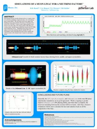
DPGeant simulations (D. Elvira) • Fully “realistic” transverse and longitudinal fields • Magnetic fields formed by current coils • Rf fields from pillbox cavities (within solenoidal coils • Studied varying number of different rf cavities in Buncher • (60 (1/m) to 20 to 10) … 20 was “better”, 10 only a bit worse • Simulations of -E rotation • Will extend simulations + optimization through cooling channel
Beam at end of Buncher 64.9 % of the particles survive at the end of the buncher
DP Geant results – rf rotation • First rf rotation with DPGeant
Hardware For Adiabatic Buncher • Transverse focussing (currently) • B=1.25T solenoidal focusing • R=0.30m transport for beam Rf requirements: • Buncher: ~300~200 MHz; 0.14.8MV/m (60m) (initially 1 cavity every 1m; reduces frequency in 2-4MHZ steps; 1-D and other early simulations indicate ~10 frequencies are sufficient (~10MHz intervals) • Rotator: 230220 MHz; 10MV/m (~10m)
RF requirements for High-frequency buncher and phase rotation
Transport requirements • Baseline example has 1.25 T solenoid for entire transport (drift + buncher + rf rotation) (~170m) • Uncooled -beam requires 30cm radius transport (100m drift with 30cm IR – 1.25T) • In simulations, solenoid coils are wrapped outside rf cavities. (~70m 1.25T magnet with 65cm IR) • FODO (quad) transport could also be used …
Cost of Solenoid (PDG handbook) • Stored Energy: • Cost: • Combine 2 solenoids: 3.5 + 7.9 = 11.4 M$ • Multiply by ~2 ~20 M$ ? • (D. Summers can do Al solenoids for ~10 M$)
Cost of magnets (M. Green) • 100m drift: 11.9 M$ (based on study 2) • Buncher and phase rotation: 26 M$ (study 2) • Cryosystem: 1.5M$; Power supplies 0.5M$ • Total Magnet System : 40M$
$$ Cost Savings ?? • High Frequency -E Rotation replaces Study 2: • Decay length (20m, 5M$) • Induction Linacs + minicool (350m, 320M$) • Buncher (50m, 70M$) • Replaces with: • Drift (100m) • Buncher (60m) • Rf Rotator (10m) • Rf cost =30M$; magnet cost =40M$ Conv. Fac. 10M$ Misc. 10M$ …… • Back of the envelope: (400M$ ?? 100M$ )
Summary • High-frequency Buncher and E Rotation simpler and cheaper than induction linac system • Performance probably not as good as study 2, But • System will capture both signs (+, -) • To do: • Complete simulations with match into cooling channel! • Optimizations • Scenario reoptimization