Download
1 / 16
160 likes | 279 Vues
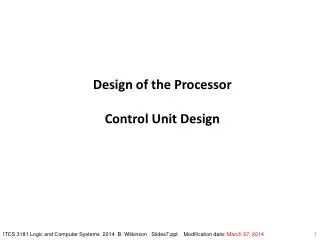
Design of the Control Unit for One-cycle Instruction Execution. The simple datapath with the control unit.

E N D
Design of the Control Unit for One-cycle Instruction Execution \course\cpeg323-05F\Topic5a-323.ppt
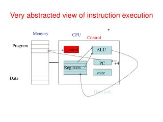
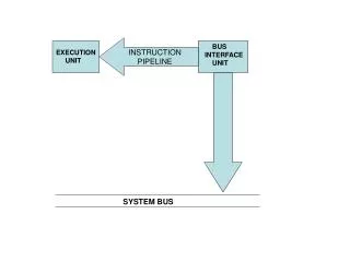
The simple datapath with the control unit. \course\cpeg323-05F\Topic5a-323.ppt
The function of each of the seven control signals. When the 1-bit control to a two-way multiplexor is asserted, the multiplexor selects the input corresponding to 1. Otherwise, if the control is deserted, the multiplexor selects the 0 input. Remember that the state elements all have the clock as an implicit input and that the clock is used in controlling writes. \course\cpeg323-05F\Topic5a-323.ppt
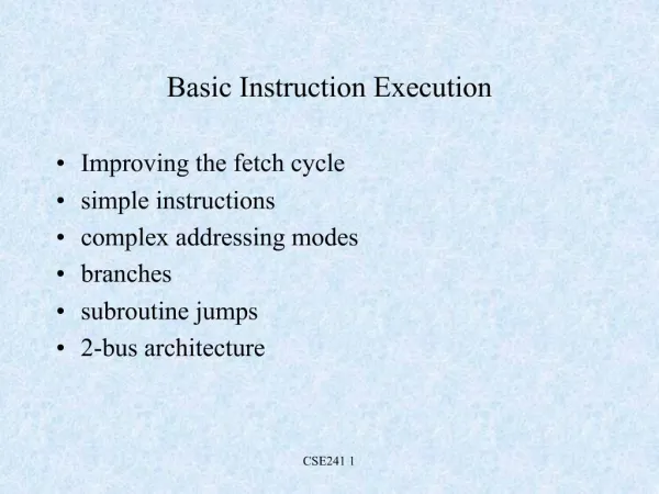
Instruction Execution • R-type: add $x, $y, $z 4 steps • I-type: lw $x, offset ($y) 5 steps \course\cpeg323-05F\Topic5a-323.ppt
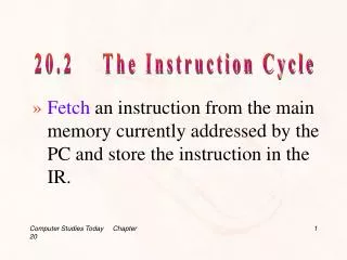
ALU Instruction Execution add $x, $y, $z 1. Instruction Fetch (IF): An instruction is fetched from the instruction memory and the PC is incremented. 2. Instruction Decode (ID): Two registers, $y and $z, are read from the register file. 3. Execution (EX): The ALU operates on the data read from the register file, using the function code (bits 5-0 of the instruction) to generate the ALU function. 4. Write Back (WB): The result from the ALU is written into the register file using bits 15-11 of the instruction to select the destination register ($x). \course\cpeg323-05F\Topic5a-323.ppt
The first step of an R-type instruction performs a fetch from instruction memory and increments the PC. \course\cpeg323-05F\Topic5a-323.ppt
The second phase in the execution of R-type instruction reads the two source registers from the register file. \course\cpeg323-05F\Topic5a-323.ppt
The third phase of execution for R-type instruction involves the ALU operating on the register data operands. \course\cpeg323-05F\Topic5a-323.ppt
The final step in an R-type instruction, writing the result, is added to the active units shown for the previous three steps . \course\cpeg323-05F\Topic5a-323.ppt
Memory Instruction Execution lw $x, offset ($y) 1. Instruction Fetch (IF): An instruction is fetched from the instruction memory and the PC is incremented. 2. Instruction Decode (ID): A register ($y) value is read from the register file. 3. Address Calculation (EX): The ALU computes the sum of the value read from the register file and the sign-extended lower 16 bits of the instruction (offset). 4. Memory Operation (MEM): The sum from the ALU is used as the address for the data memory. 5. Write Back (WB): The data from the memory unit is written into the register file; the register destination is given by bits 20-16 of the instruction ($x). \course\cpeg323-05F\Topic5a-323.ppt
The operation of a load instruction with the simple datapath control scheme. \course\cpeg323-05F\Topic5a-323.ppt
Branch Instruction Execution beq $x, $y, offset 1. Instruction Fetch (IF): An instruction is fetched from the instruction memory and the PC is incremented. 2. Instruction Decode (ID): Two registers, $x and $y, are read from the register file. 3. Branch Address calculation (EX): The ALU performs a subtract on the data values read from the register file. The value of PC + 4 is added to the sign-extended lower 16 bits of the instruction (offset); the result is the branch target address. 4. Branch Decision: The Zero result from the ALU is used to decide which adder result to store into the PC. \course\cpeg323-05F\Topic5a-323.ppt
The datapath in operation for a branch equal instruction. \course\cpeg323-05F\Topic5a-323.ppt
Control Unit Design RegDst ALUSrc 0p5 Control ALU0p1 ALU0p0 0p0 \course\cpeg323-05F\Topic5a-323.ppt
The control function for the simple one-clock implementation is completely specified by this truth table. The top half of the table gives the combinations of input signals that correspond to the four opcodes that determine the control output setting. (Remember that Op (5-0) corresponds to bits 31-26 of the instruction, which is the opcode field.) The bottom portion of the table gives the outputs. \course\cpeg323-05F\Topic5a-323.ppt
The simple control and datapath are extended to handle the jump instruction. \course\cpeg323-05F\Topic5a-323.ppt