Download
1 / 39
400 likes | 903 Vues
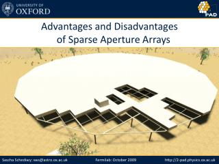
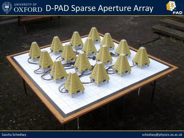
D-PAD Sparse Aperture Array. Presentation Overview. D-PAD Aims What is D-PAD? Advantages of this design Recent results Future work. D-PAD Aims. Broadband SKA test system which will work in RFI environment Develop an SKA 1 AA-low compatible digital back-end processing system

E N D
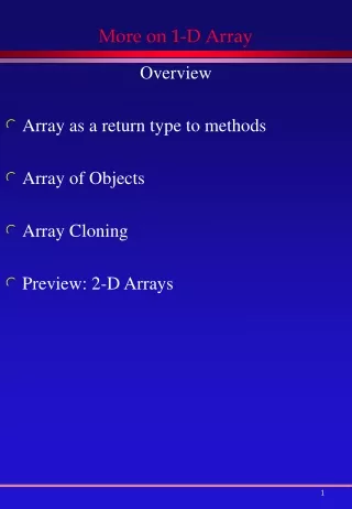
Presentation Overview • D-PAD Aims • What is D-PAD? • Advantages of this design • Recent results • Future work
D-PAD Aims • Broadband SKA test system which will work in RFI environment • Develop an SKA1 AA-low compatible digital back-end processing system • Experimentally quantify the effect of side lobes on imaging dynamic range • Investigate novel direct imaging correlator algorithms • Compare calibration issues of aperture arrays with dishes of similar frequency
What is D-PAD? • D-PAD = Danny’s PhD Aperture-array Demonstrator • Key Values: • f = 1000-1500MHz, 8 stations/tiles, sparse high-gain antennas the first tile
What is D-PAD? • Least complex instrument possible that replicates most key aspects of an SKA aperture array • Flexible and reconfigurable hardware and software • Testbed for comparing measurements with simulations • Digital system can be recycled forAA-low and AA-mid test systems • Science with AA-high feasibility study;transients, solar, local HI, pulsars?
D-PAD High Gain Antenna • Antenna element beam pattern@1300MHz) • Half power beam width: ±24°, directivity: 8.45dBi, sidelobe: -15dB, front-to-back: -18dB , ellipticity: 8%
D-PAD Analogue System X-Polarisation Y-Polarisation antenna blade antenna blade antenna blade antenna blade LNA LNA LNA LNA 2-way 0° combiner 2-way 0° combiner amp2 amp2 coax coax 16-way 0° beamformer 16-way 0° beamformer filter filter gain block gain block coax coax gain block gain block filter filter gain block gain block coax coax
D-PAD Digital System X1 Y1 X2 Y2 X3 Y3 X4 Y4 X5 Y5 X6 Y6 X7 Y7 X8 Y8 iADC iADC iADC iADC iADC iADC iADC iADC ROACH ROACH ROACH ROACH F F F F F F F F F F F F F F F F 10GbE 10GbE 10GbE 10GbE 16-port 10GbE switch 10GbE ROACH X 10GbE data acquisition computer Image credits CASPER
D-PAD Digital System • Complimentary spectrometer designs • Milli-second, fast transient spectrometer design will be incorporated shortly Image credits CASPER
Advantages of this Design • High-gain antenna results in greater sensitivity • also reduces impact of sparse array grating lobes • higher imaging dynamic range than sparse arrays with omni-directional antennas • Sparse aperture arrays have faster survey speed • small diameter stations = larger intrinsic Field-of-View than dishes of same total collecting area: FoV = π (1.22*λ/d)2 • Wide radio frequency bandwidth (500MHz) • greater continuum sensitivity, greater flexibility(compare with LOFAR and MWA; 32MHz ) • Greater sensitivity for line surveys at higher redshift • full collecting area over entire bandwidth: Aeff = Gλc2/4π
Advantages of this Design • Analogue beamformer reduces cost • fewer receiver chains, less power, less computation • Fast ADCs means no complicated down conversion • Direct sampling in 3rd Nyqusit zone (same digital hardware as 30-470MHz SKA AA-low system) • Novel correlators reduce computational cost • direct imaging correlators MOFF or FFTT (close-packed tiles can use Fourier transform on a spatial grid ) • MOFF can use FFT while traditional FX correlator must use DFT • Higher operating frequency, less demanding calibration • lower sky brightness temperature, fewer bright in foreground subtraction, less complex polarisation calibration
D-PAD Frequency Spectrum 40 30 20 10 0 Arb. Power (dB) 1000 1100 1200 1300 1400 1500 Frequency (MHz)
Continuum Observations • 20,000 spectra per polarisation over 5 days with 20s integration time
21cm Neutral Hydrogen Line • 10,000 spectra per polarisation over 3 days with 17s integration time
Future Work • Detailed analysis of observations • Millisecond transient spectrometer • Array beam pattern measurement • Construction of 8-tile system
Advantages of this Design • Greater sensitivity for line surveys at higher redshift • full collecting area over entire bandwidth • effective area: • Aeff = Gλc2/4π
D-PAD Digital System X1 Y1 X2 Y2 Analogue to Digital Analogue to Digital Finite Impulse Response Band-Pass Filter Fast Fourier Transform Real Convert to Power Convert to Power Vector Accumulate Vector Accumulate Cast/Slice Cast/Slice BRAM BRAM BRAM BRAM Packetise to 10GbE
D-PAD Analogue Components • LPDA Antenna (at boresight)
D-PAD Analogue Components • Receiver Board (noise temperature ≈ 35K)
D-PAD Analogue Components • Gain Amplifier
D-PAD Analogue Components • Band-Pass Filter
D-PAD Analogue Components • Beam-Forming Combiner
D-PAD Analogue Components • Coaxial Cable A and C
D-PAD Analogue Components • Coaxial Cable B
D-PAD Analogue System • Total Gain
Station beam pattern Grating Lobes BeamPower Station Beam Pattern • Antenna separation: random (f > 1) dense (f < 1) nominal (f = 1) sparse (f > 1) Antenna Element Separation [SKA Memo 87]
Instantaneous Field of View • 60m Dish + Phased Array Feed • 120deg+10,000deg2+ • 18deg250deg2 • Fully Digital Dense A. Array • 120deg10,000deg2 • 18deg250deg2 • Hybrid Dense A. Array • 120deg10,000deg2 • 28deg 625deg2 • 18deg250deg2 • Sparse High Gain A. Array • 36deg1,000deg2 • 18deg250deg2
fc= 300MHz Effective Area • Effective Area: Aeff (θ,φ) = G (θ,φ) λc2/4π Effective Area per Element sparse limit fc dense up to fc = 700MHz fc dense up to fc = 1000MHz [SKA Memo 100]
Sky Brightness Temperature • Tsky = 5e8 * f -2.861 + 4 SKA Memo 95 by Germán Cortés Medellín.
Sensitivity • SKA Phase 1 Sensitivity
D-PAD X-Polarisation Y-Polarisation antenna blade antenna blade antenna blade antenna blade LNA LNA LNA LNA 2-way 0° combiner 2-way 0° combiner amp2 amp2 coax coax 2-way 0° combiner filter gain block coax gain block filter gain block coax iADC ROACH F 10GbE GPU dispersion measure PC