Download
1 / 74
820 likes | 1.4k Vues
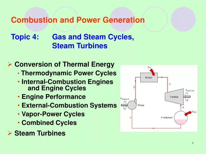
Combustion and Power Generation Topic 4: Gas and Steam Cycles, Steam Turbines. Conversion of Thermal Energy Thermodynamic Power Cycles Internal-Combustion Engines and Engine Cycles Engine Performance External-Combustion Systems Vapor-Power Cycles Combined Cycles Steam Turbines.

E N D
Combustion and Power Generation Topic 4: Gas and Steam Cycles, Steam Turbines • Conversion of Thermal Energy • Thermodynamic Power Cycles • Internal-Combustion Engines and Engine Cycles • Engine Performance • External-Combustion Systems • Vapor-Power Cycles • Combined Cycles • Steam Turbines
Conversion of Thermal Energy • Almost all of the mechanical energy produced today is produced from the conversion of thermal energy in some sort of heat engine. • The operation of all heat-engine cycles can usually be approximated by an ideal thermodynamic power cycle of some kind. • A basic understanding of these cycles can often show the power engineer how to improve the operation and performance of the system.
Thermodynamic Power Cycles • For a thermodynamic heat-engine cycle, the figure of merit is called the thermal efficiency, or hth. The desired energy output is the net work output of the cycle and the energy that costs is the heat added from the high-temperature heat sources. • Another important parameter of any heat-engine cycle is the specific work, w, which is the net work output per pound of working fluid in the cycle. It is also equal to the area enclosed by the cycle diagram when it is plotted on either a P-v or T-s diagram, providing the mass flow rate of the working fluid is the same throughout the cycle and the processes are reversible.
P- and T-s Diagrams of Power Cycles The area under the heat addition process on a T-s diagram is a geometric measure of the total heat supplied during the cycle qin, and the area under the heat rejection process is a measure of the total heat rejected qout. The difference between these two (the area enclosed by the cyclic curve) is the net heat transfer, which is also the net work produced during the cycle.
Reversible Heat-Engine Cycles • The second law of thermodynamics states that it is impossible to construct a heat engine or to develop a power cycle that has a thermal efficiency of 100%. This means that at least part of the thermal energy transferred to a power cycle must be transferred to a low-temperature sink. • There are four phenomena that render any thermodynamic process irreversible. They are: • Friction • Unrestrained expansion • Mixing of different substances • Transfer of heat across a finite temperature difference
Categorize Cycles • Thermodynamic cycles can be divided into two general categories: Power cycles and refrigeration cycles. • Thermodynamic cycles can also be categorized as gas cycles or vapor cycles, depending upon the phase of the working fluid. • Thermodynamic cycles can be categorized yet another way: closed and open cycles. • Heat engines are categorized as internal or external combustion engines.
Air-Standard Assumptions • To reduce the analysis of an actual gas power cycle to a manageable level, we utilize the following approximations, commonly know as the air-standard assumptions: • The working fluid is air, which continuously circulates in a closed loop and always behaves as an ideal gas. • All the processes that make up the cycle are internally reversible. • The combustion process is replaced by a heat-addition process from an external source. • The exhaust process is replaced by a heat rejection process that restores the working fluid to its initial state.
Air-Standard Cycle Another assumption that is often utilized to simplify the analysis even more is that the air has constant specific heats whose values are determined at room temperature (25oC, or 77oF). When this assumption is utilized, the air-standard assumptions are called the cold-air-standard assumptions. A cycle for which the air-standard assumptions are applicable is frequently referred to as an air-standard cycle. The air-standard assumptions stated above provide considerable simplification in the analysis without significantly deviating from the actual cycles. The simplified model enables us to study qualitatively the influence of major parameters on the performance of the actual engines.
Mean Effective Pressure The ratio of the maximum volume formed in the cylinder to the minimum (clearance) volume is called the compression ratio of the engine. Notice that the compression ratio is a volume ratio and should not be confused with the pressure ratio. Mean effective pressure (MEP) is a fictitious pressure that, if it acted on the piston during the entire power stroke, would produce the same amount of net work as that produced during the actual cycle.
Three Ideal Power Cycles • Three ideal power cycles are completely reversible power cycles, called externally reversible power cycles. These three ideal cycles are the Carnot cycle, the Ericsson cycle, and the Stirling Cycle.
Three Ideal Power Cycles • The Carnot cycle is an externally reversible power cycle and is sometimes referred to as the optimum power cycle in thermodynamic textbooks. It is composed of two reversible isothermal processes and two reversible adiabatic (isentropic) processes. • The Ericsson power cycle is another heat-engine cycle that is completely reversible or “externally reversible.” It is composed of two reversible isothermal processes and two reversible isobaric processes (with regenerator). • The Stirling cycle is also an externally reversible heat-engine cycle and is the only one of the three ideal power cycles that has seen considerable practical application. It is composed of two reversible isothermal processes and two reversible isometric (constant volume) processes.
Carnot Cycle and Its Value in Engineering The Carnot cycle is composed of four totally reversible processes: isothermal heat addition, isentropic expansion, isothermal heat rejection, and isentropic compression (as shown in the P- diagram at right). The Carnot cycle can be executed in a closed system (a piston-cylinder device) or a steady-flow system (utilizing two turbines and two compressors), and either a gas or vapor can be used as the working fluid.
Limit of TH and TL in a Carnot Cycle Thermal efficiency increases with an increase in the average temperature at which heat is supplied to the system or with a decrease in the average temperature at which heat is rejected from the system. The highest temperature in the cycle is limited by the maximum temperature that the components of the heat engine, such as the piston or turbine blades, can withstand. The lowest temperature is limited by the temperature of the cooling medium utilized in the cycle such as a lake, a river, or atmospheric air.
Internal-Combustion Engine Cycles • Internal-combustion (IC) engines cannot operate on an ideal reversible heat-engine cycle but they can be approximated by internally reversible cycles in which all the processes are reversible except the heat-addition and heat-rejection processes. • In general, IC engines are more polluting than external-combustion (EC) engines because of the formation of nitrogen oxides, carbon dioxide, and unburned hydrocarbons. • The Otto cycle is the basic thermodynamic power cycle for the spark-ignition (SI), internal-combustion engine.
Otto Cycle: The ideal Cycle for Spark-Ignition Engines Figures below show the actual and ideal cycles in spark-ignition (SI) engines and their P- diagrams.
Ideal Otto Cycle The thermodynamic analysis of the actual four-stroke or two-stroke cycles can be simplified significantly if the air-standard assumptions are utilized. The T-s diagram of the Otto cycle is given in the figure at left. The ideal Otto cycle consists of four internally reversible processes: 12 Isentropic compression 23 Constant volume heat addition 34 Isentropic expansion 41 Constant volume heat rejection
Thermal Efficiency of an Otto Cycle The Otto cycle is executed in a closed system, and disregarding the changes in kinetic and potential energies, we have
Engine Knockand thermal Efficiency of an Engine The thermal efficiency of the ideal Otto cycle increases with both the compression ratio and the specific heat ratio. • When high compression ratios are used, the temperature of the air-fuel mixture rises above the autoignition temperature produces an audible noise, which is called engine knock. (antiknock, tetraethyl lead? unleaded gas) • For a given compression ratio, an ideal Otto cycle using a monatomic gas (such as argon or helium, k = 1.667) as the working fluid will have the highest thermal efficiency.
Example IV-4.1: The Ideal Otto Cycle An ideal Otto cycle has a compression ratio of 8. At the beginning of the compression process, the air is at 100 kPa and 17oC, and 800 kJ/kg of heat is transferred to air during the constant-volume heat-addition process. Accounting for the variation of specific heats of air with temperature, determine a) the maximum temperature and pressure that occur during the cycle, b) the net work output, c) the thermal efficiency, and d) the mean effective pressure for the cycle. <Answers: a) 1575.1 K, 4.345 MPa, b) 418.17 kJ/kg, c) 52.3%, d) 574.4 kPa> Solution:
Diesel Cycle: The Ideal Cycle for Compression-Ignition Engines The diesel cycle is the ideal cycle for CI (Compression-Ignition) reciprocating engines. The CI engine first proposed by Rudolph Diesel in the 1890s, is very similar to the SI engine, differing mainly in the method of initiating combustion. In SI engines (also known as gasoline engines), the air-fuel mixture is compressed to a temperature that is below the autoignition temperature of the fuel, and the combustion process is initiated by firing a spark plug. In CI engines (also known as diesel engines), the air is compressed to a temperature that is above the autoignition temperature of the fuel, and combustion starts on contact as the fuel is injected into this hot air. Therefore, the spark plug and carburetor are replaced by a fuel injector in diesel engines.
Ideal Cycle for CI Engines (continued) In diesel engines, ONLY air is compressed during the compression stroke, eliminating the possibility of autoignition. Therefore, diesel engines can be designed to operate at much higher compression ratios, typically between 12 and 24. The fuel injection process in diesel engines starts when the piston approaches TDC and continues during the first part of the power stroke. Therefore, the combustion process in these engines takes place over a longer interval. Because of this longer duration, the combustion process in the ideal Diesel cycle is approximated as a constant-pressure heat-addition process. In fact, this is the ONLY process where the Otto and the Diesel cycles differ.
Thermal efficiency of Ideal Diesel Cycle Under the cold-air-standard assumptions, the efficiency of a Diesel cycle differs from the efficiency of Otto cycle by the quantity in the brackets. (See Slide #26) The quantity in the brackets is always greater than 1. Therefore, hth,Otto > hth, Dieselwhen both cycles operate on the same compression ratio. Also the cuttoff ratio, rc decreases, the efficiency of the Diesel cycle increases. (See figure at right)
Internal-Combustion Engines The two basic types of ignition or firing systems are the four-stroke-cycle engines, commonly called four-cycle engines, and the two-stroke-cycle engines, commonly called two-cycle engines. The four-cycle engines has a number of advantages over the usual two-cycle engine, including better fuel economy, better lubrication, and easier cooling. The two-cycle engine has a number of advantages, including fewer moving parts, lighter weight, and smoother operation. Some two-cycle engines have valves and separate lubrication systems.
Cylinder Arrangements for Reciprocating Engines Figure below shows schematic diagrams of some of the different cylinder arrangements for reciprocating engines.
Vertical in-line engine is commonly used today in four- and six-cylinder automobile engines. • The V-engine is commonly employed in eight-cylinder (V-8) and some six-cylinder (V-6) automobile engines. • The horizontal engine is essentially a V-engine with 180o between the opposed cylinders. This system was used as the four-cylinder, air-cooled engine that powered the Volkswagon “bug”. • The opposed-piston engine consists of two pistons, two crankshafts, and one cylinder. The two crankshafts are geared together to assure synchronization. These opposed-piston systems are often employed in large diesel engines.
The delta engine is composed of three opposed-piston cylinders connected in a delta arrangement. These systems have found application in the petroleum industry. • The radial engine is composed of a ring of cylinders in one plane. One piston rod, the “master” rod, is connected to the single crank on the crankshaft and all the other piston rods are connected to the master rod. Radial engines have a high power-to-weight ratio and were commonly employed in large aircraft before the advent of the turbojet engine. • When the term “rotary engine” is used today, it implies something other than a radial engine with a stationary crank.
Engine Performance There are several performance factors that are common to all engines and prime movers. One of the main operating parameters of interest is the actual output of the engine. The brake horsepower (Bhp) is the power delivered to the driveshaft dynamometer. The brake horsepower is usually measured by determining the reaction force on the dynamometer and using the following equation: Where F is the net reaction force of the dynamometer, in lbf, R is the radius arm, in ft, and Ndis the angular velocity of the dynamometer, in rpm.
Horsepower For a particular engine, the relationship between the mean effective pressure (mep) and the power is: Where C is the number of cylinders in the engine, Ne is the rpm of the engine, and z is equal to 1 for a two-stroke-cycle engine and 2 for a four-stroke-cycle engine.
Brake Thermal Efficiency The brake thermal efficiency of an engine, hth, unlike power plants, is usually based on the lower heating value (LHV) of the fuel. The relationship between efficiency and the brake specific fuel consumption (Bsfc) is: Note that the brake specific fuel consumption (Bsfc) of an engine is a measure of the fuel economy and is normally expressed in units of mass of fuel consumed per unit energy output.
External-Combustion Systems External-combustion power systems have several advantages over internal-combustion systems. In general, they are less polluting. The primary pollutants from internal-combustion engines are unburned hydrocarbons, carbon monoxide, and oxides of nitrogen. In external-combustion engines, the CHx and CO can be drastically reduced by carrying out the combustion with excess air and the NOx production can be markedly reduced by lowering the combustion temperature. By burning the fuel with excess air, more energy is released per pound of fuel. There are three general ideal external-combustion engine cycles, the Stirling and Brayton are ideal gas-power, and vapor power cycles.
Brayton Cycle: The Ideal Cycle for Gas-Turbine Engines The Brayton cycle was first proposed by George Brayton for use in the reciprocating oil-burning engine that he developed around 1870. Fresh air at ambient conditions is drawn into the compressor, where its temperature and pressure are raised. The high- pressure air proceeds into the combustion chamber, where the fuel is burned at constant pressure. The resulting high-temperature gases then enter the turbine, where they expand to the atmospheric pressure, thus producing power. (An open cycle.)
Brayton Cycle (continued) The open gas-turbine cycle can be modeled as a closed cycle, as shown in the figure below, by utilizing the air-standard assumptions. The ideal cycle that the working fluid undergoes in this closed loop is the Brayton cycle, which is made up of four internally reversible processes: 12 Isentropic compression (in a compressor) 23 Constant pressure heat addition 34 Isentropic expansion (in a turbine) 41 Constant pressure heat rejection
T-s Diagram of Ideal Brayton Cycle Notice that all four processes of the Brayton cycle are executed in steady-flow devices (as shown in the figure on the previous slide, T-s diagram at the right), and the energy balance for the ideal Brayton cycle can be expressed, on a unit-mass basis, as
P- Diagram and th of Ideal Brayton Cycle Then the thermal efficiency of the ideal Brayton cycle under the cold-air-standard assumptions becomes
Thermal Efficiency of the Ideal Brayton Cycle Under the cold-air-standard assumptions, the thermal efficiency of an ideal Brayton cycle increases with both the specific heat ratio of the working fluid (if different from air) and its pressure ratio (as shown in the figure at right) of the isentropic compression process. The highest temperature in the cycle occurs at the end of the combustion process, and it is limited by the maximum temperature that the turbine blades can withstand. This also limits the pressure ratios that can be used in the cycle.
Net Work of the Brayton Cycle For a fixed turbine inlet temperature T3, the net work output per cycle increases with the pressure ratio, reaches a maximum, and then starts to decrease, as shown in the figure at right. Therefore, there should be a compromise between the pressure ratio and the net work output. In most common designs, the pressure ratio of gas turbines ranges from about 11 to 16.
The Back Work Ratio A power plant with a high back work ratio requires a larger turbine to provide the additional power requirements of the compressor. Therefore, the turbine used in gas-turbine power plants are larger than those used in steam power plants of the same net power output. In gas-turbine power plants, the ratio of the compressor work to the turbine work, called the back work ratio, is very high. Usually more than half of the turbine work output is used to drive the compressor. The two major application areas of gas-turbine engines are aircraft propulsion and electric power generation.
Development of Gas Turbines The efforts to improve the cycle efficiency concentrated in three areas: Increasing the turbine inlet (or firing) temperature (high NOx!?) which can be achieve by the development of new materials and the innovative cooling techniques. Increasing the efficiencies of turbo-machinery components. Adding modifications to the basic cycle such as incorporating intercooling, regeneration, and reheating techniques. A more recent gas turbine manufactured by GE use 1425oC turbine inlet temperature, 282 MW, and 39.5% efficiency in the simple-cycle mode.
Deviation of Actual Gas-Turbine Cycles from Idealized Ones The deviation of actual compressor and turbine behavior from the idealized isentropic behavior can be accurately accounted for by utilizing the isentropic efficiencies of the turbine and compressor defined as (equations at bottom right). Where states 2a and 4a are the actual exit states of the compressor and the turbine, respectively, and 2s and 4s are the corresponding states for isentropic case.
The Brayton Cycle with Regeneration In gas-turbine engines, the temperature of the exhaust gas leaving the turbine is often considerably higher than the temperature of the air leaving the compressor. Therefore, the high-pressure air leaving the compressor can be heated by transferring heat to it from the hot exhaust gases in a counter-flow heat exchanger, which is also known as a regenerator or a recuperator (as shown in the figure above.)
T-s Diagram of a Brayton Cycle with Regeneration The thermal efficiency of the Brayton cycle increases as a result of regeneration since the portion of energy of the exhaust gases that is normally rejected to the surroundings is now used to preheat the air entering the combustion chamber.
Thermal Efficiency of the Ideal Brayton Cycle with and without Regeneration The use of a regenerator with a very high effectiveness (0.85 in practice) cannot be justified economically unless the savings from the fuel costs exceed the additional expense involved. Under the cold-air-standard assumptions, the thermal efficiency of an ideal Brayton cycle with regeneration is shown at right, which operates most effectively at lower rp and (T1/T3) ratios.
Rankine Cycle: The Ideal Cycle for Vapor Power Cycles Many of the impracticalities associated with the Carnot cycle can be eliminated by superheating the steam in the boiler and condensing it completely in the condenser, as shown schematically on a T-s diagram in the figure (on next slide). The cycle that results is the Rankine cycle, which is the ideal cycle for vapor power plants.
Rankine Cycle (continued) The Ideal Rankine cycle does not involve any internal irreversibilities and consists of the following four processes: 12 Isentropic compression in a pump 23 Constant pressure heat addition in a boiler (steam generator) 34 Isentropic expansion in a turbine 41 Constant pressure heat rejection in a condenser (water or dry air cooling)
Energy Analysis of the Ideal Rankine Cycle All four processes that make up the Rankine cycle can be analyzed as steady-flow processes. The steady-flow energy equation per unit mass of steam reduces to The boiler and the condenser do not involve any work, and the pump and the turbine are assumed to be isentropic, thus,


![An Introduction To Marine Steam Propulsion Plant [Source: US Navy]](https://cdn0.slideserve.com/482243/an-introduction-to-marine-steam-propulsion-plant-source-us-navy-dt.jpg)