Download
1 / 21
210 likes | 352 Vues
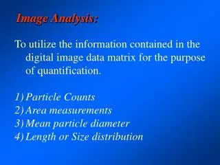
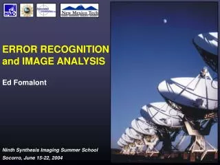
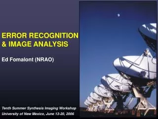
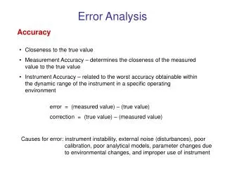
Image Error Analysis. Fourier-domain analysis of errors. 2-D Fourier transform concepts Examples of errors in UV-plane and image plane. Some common ATCA image errors. Circular. Errors occur in the visibility (uv) domain. These errors are Fourier transformed into the image. Circular.

E N D
Image Error Analysis • Fourier-domain analysis of errors. • 2-D Fourier transform concepts • Examples of errors in UV-plane and image plane. • Some common ATCA image errors.
Circular Errors occur in the visibility (uv) domain. These errors are Fourier transformed into the image. Circular Broad Narrow Fourier–domain Analysis Crap Crap
Bad Scan - Visibilities: Unflagged: Flagged: Only two scans on 1/15 baselines affected.
Bad Scan - Images: Unflagged: Flagged:
Bad Gain - Visibilities: 2.5% Gain error: Properly Calibrated: Gain error affects all visibilities on 5/15 baselines
Bad Gain - Visibilities: 2.5% Gain error: Properly Calibrated:
Does this make sense!? • Broad component, • High spatial frequency structure, • Circular form.
UV Distribution of Errors Baselines to antenna 5 in red.
No short baselines Effect of missing short baselines
Inadequate UV Coverage: • ATCA: • No gain/phase errors. • 8 hours • Declination –15°
CLEAN 3 clean boxes 1000 iterations MAXEN 3 boxes 30 iterations Inadequate UV coverage:
Use different array configuration. Different frequency, if possible. North-spur, when available. Recognizing Poor UV Coverage: • Fourier Transform the Source Model and Beam!
Other things to consider: • Check your calibrators!! • Resolved • Intra-day variability! • Elevation dependent gains • Esp. atmospheric opacity at high frequencies. • Primary beam • Images attenuated away from image centre. • Antenna gain very sensitive near half-power.
Summary • Errors occur in the UV-domain. • An error which looks bad in the visibilities might not give a bad image error. • An error which is invisible in the visibilities might have a dramatic effect on the image. • Be awake, be skeptical. • Have fun!