Download
1 / 16
940 likes | 5.05k Vues
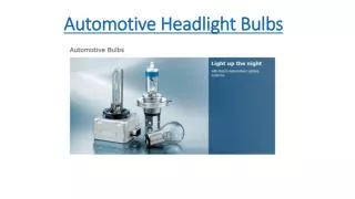
Adaptive Headlight System. Betzayda Rivera Projects II Design Review Tuesday, 9-16-03. Background. Currently, Headlights shine directly in front of a vehicle The high to low beam transition is manual In general, the same beam shines all the time just at different intensities .

E N D
Adaptive Headlight System Betzayda Rivera Projects II Design Review Tuesday, 9-16-03
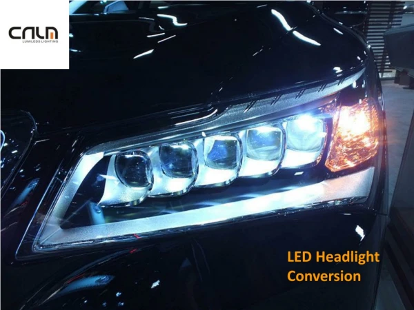
Background • Currently, • Headlights shine directly in front of a vehicle • The high to low beam transition is manual • In general, the same beam shines all the time just at different intensities
Project Objectives • To ENHANCE the existing functionality • Improve VISIBILITY • Decrease number of night time accidents • Increase SAFETY for drivers & pedestrians
First Feature • Adaptive Headlights: • BMW animation
Second Feature • High to Low beam transition: • High => Low with oncoming traffic or city environment • Low => High after lighted situation passes • How? Light/Dark Sensor
Third Enhancement • Speed Controlled Beam Orientation: • Narrow & lengthen the beam at HIGH speeds • Widen & shorten the beam at LOW speeds • How? Secondary Reflector
Analysis & Specifications • Vishay Spectrol • Full 360 degree Smart Position Sensor • Light Sensor • Two methods under experimentation • Darlington Light Sensor • Cricket Light Sensor • Four Servo Motors • Two to control large reflective plate • Two to control smaller outer reflector
Electrical Component Supply Voltage 4.5 to 5.5 VDC Supply Current 20 mA max Resolution min of 0.5 degrees Electrical Track 360 degrees continuous Analog Vout > 90% of supply Output Impedence 1 ohm typically Mechanical Component Rotation 360 degrees continuous Rotational Speed 5 max revs/sec for 60sec Max Torque 3.68 (0.5) mNm (oz in) Weight 30 gm Environmental Component Operating Life 5,000,000 Cycles Analysis & Specifications • Vishay Spectrol Smart Position Sensor
Darlington Cricket Analysis & Specifications SW1 = Toggle switch R1 = LDR R2 = 10k ohm R3 = 1k ohm VR1 = 10k ohm BZ1 = Buzzer D1 = Diode (1N4001) Transistor = (TIP 121)
Analysis & Specifications • Two Large Inner Reflective Plates • Used to aim the headlight during turns • Servo positioned in center; weight distribution • 45 degree total mobility • Two Small Outer Reflective Plates • Used to narrow or widen beam by speed • Servo positioned in center; weight distribution • 30 degree total mobility
Power Consumption Relatively Low Power Stationary System; therefore Utilize Wall Power.
Scheduled Work Task Actual Completion Date Week 1 Final Proposal Due (R 9.11.03 10a) 9.10.03 Week 1 Investigate and Select Sensors & Actuators 9.15.03 Week 1 Prepare HC12 for program simulation with lamp/switch board Week 1/2 Begin Website Creation 9.12.03 Week 2 Design Review Presentation (T 9.16.03 10a) 9.16.03 After Design Review Week 2 (9.16.03) Finalize Component List and Methods; Update Proposal Week 2 (9.20.03) Acquire Components 9.15.03 (begun) Week 2 Begin HC12 Simulations Week 2 (9.17.03) Acquire Test data Week 2 (9.18.03) Experiment with servo/mechanical method to move reflectors or find better method Week 3 Experiment with sensors Week 3 Build encasing and headlight setups; Test separate from HC12 Week 4 Interface tested physical components to HC12 Week 5 Connect all components together & test full sys. Demo Prep. Week 6 Prepare what is left of Write Up & Demo. Timeline
Test Plan • Test Data • Steering wheel rotation vs headlight movement • Light/Dark standards and cutoffs • Vishay Spectoral Rotational Position Sensor • Test alone • Test with servos and HC12 for position analysis • Test with servos and load to calibrate
Test Plan • Sensors • Darlington Light sensor circuit is equip with a buzzer for independent testing • Cricket Light sensor setup designed light an LED when active then HC12 beep during demo for audio indication • Servos • Expansion from Projects I; test with load for available torque and repeatability
Safety Concerns Purpose is to ENHANCE the safety of all!!
Component Priced Paid Expected Price HC12 MicroController RIT $150 Servo Motors (2) $30 $15 /each Servo Motors (2) RIT $8 /each Light Sensor (Darlington) $10 setup Cricket Light Sensor (CDS Photocell, heat shrink, 3 position connector) $10 setup Smart Position Sensor (Vishay Spectrol) sample ~ $300 /each Steering wheel and column (junk yard) $20 Mirrors (2 long ; 2 short) $15 /all Light Bulbs (4) $30 Headlight encasings (junkyard) $20 Light Meter for tabulating data & testing RIT $70 2x4 wood beams for mounting $10 External Lighting for testing & demo PreOwned $15 Batteries (flashlights, etc) $10 Misc (screws, wire, solder, R, C, etc) $30 Total Expected System Cost ($736)