Download
1 / 63
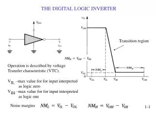
630 likes | 739 Vues
The Digital Logic Level. Chapter 3. PCI Bus (1). With multimedia games and full-motion video the ISA bus could not handle the amount of data transfer. A 1024x768 screen used for true color (3 bytes/pixel) moving image contains 2.25 MB of data.

E N D
The Digital Logic Level Chapter 3
PCI Bus (1) • With multimedia games and full-motion video the ISA bus could not handle the amount of data transfer. • A 1024x768 screen used for true color (3 bytes/pixel) moving image contains 2.25 MB of data. • For smooth motion, at least 30 screens/sec are needed, for a data rate of 67.5 MB/sec. • To display a video from hard disc, CD-ROM or DVD, the data must pass from the disk drive over the bus to the memory and then travel to graphics adapter. • Thus a bandwidth of 135 MB/sec is required for the video alone. • The ISA bus runs at a maximum rate of 8.33 MHz and can transfer 2 bytes per cycle, for a maximum bandwidth of 16.7 MB/sec.
PCI Bus (2) • The EISA bus can move 4 bytes per cycle, to achieve 33.3 MB/sec. • Intel designed a new bus with much higher bandwidth than EISA bus, called the PCI bus(Peripheral ComponentInterconnect bus). • The original PCI bus transferred 32 bits per cycle and ran at 33 MHz (30 nsec cycle time) for a total bandwidth of 133 MB/sec. • In 1993, PCI 2.0 was introduced and in 1995, PCI 2.1 came out. • PCI 2.2 has features for mobile computers (saving battery power) and runs at up to 66 MHz and can handle 64-bit transfers, for a total bandwidth of 528 MB/sec.
The PCI Bus (3) • Even with 528 MB/sec, PCI bus is not good enough for memory bus and is not compatible with all the old ISA cards. • Intel designed future computers with three or more buses. • Figure 3-51. Architecture of an early Pentium system. The thicker buses have more bandwidth than the thinner ones but the figure is not to scale.
PCI Bus (4) • The PCI bridge connects the CPU, memory, and PCI bus. • The ISA bridge connects the PCI bus to the ISA bus and also supports one or two IDE disks. • The advantage is that the CPU has an extremely high bandwidth to memory, using a proprietary memory bus the PCI bus has a very high bandwidth for fast peripherals such as SCSI disks, graphics adaptors, etc., and old ISA cards. • It is possible to have multiple PCI buses connected through PCI-to-PCI bridge chips. • Since there are more than one kind of PCI card, options are provided for voltage, width, and timing.
PCI Bus (5) • PCI bus supports both 5 volts used by older computers and 3.3 volts used by newer computers. • There are universal cards that support both voltages and can plug into either kind of slot. • Cards come in 32-bit and 64-bit versions. • The 32-bit cards have 120 pins; the 64-bit cards have the same 120 pins plus an additional 64 pins. • A PCI bus system that supports 64-bit cards can also take 32-bit cards, but the reverse is not true. • PCI buses and cards can run at either 33 MHz or 66 MHz. • The choice is made by having one pin wired either to the power supply or wired to ground.
PCI Bus (6) For monitor resolution of 1600 × 1200 and for full-screen full motion video AGP bus (Accelerated Graphics Port bus) was introduced. AGP 1.0, ran at 264 MB/sec, which was defined as 1x. AGP 3.0 ran at 2.1 GB/sec (8x). Today, faster PCI Express bus, gives16 GB/sec of data over high-speed serial bus links
PCI Bus in core i7 (1) A number of interfaces have been integrated directly into the CPU chip. The two DDR3 memory channels, running at 1333 transactions/sec, connect to main memory and provide an aggregate bandwidth of 10 GB/sec per channel. Also integrated into the CPU is a 16-lane PCI Express channel, which optimally can be configured into a single 16-bit PCI Express bus or dual independent 8-bit PCI Express buses. The 16 lanes together provide a bandwidth of 16 GB/sec to I/O devices. The CPU connects to the primary bridge chip, the P67, via the 20-Gb/sec serial direct media interface (DMI).
The PCI Bus (2a) • Figure 3-52. The bus structure of a modern Core i7 system.
PCI Bus in core i7 (2) The P67 provides interfaces to a number of modern high-performance I/O interfaces. Eight additional PCI Express lanes are provided, plus SATA disk interfaces. The P67 also implements 14 USB 2.0 interfaces, 10G Ethernet and an audio interface. The ICH10 chip provides legacy interface support for old devices. It is connected to the P67 via a slower DMI interface. The ICH10 implements the PCI bus, 1G Ethernet, USB ports, and old-style PCI Express and SATA interfaces.
The PCI Bus (2b) • Figure 3-52. The bus structure of a modern Core i7 system.
PCI Bus Operation (1) • The PCI bus is synchronous. • All transactions on the PCI bus are between a master, called initiator, and a slave, called the target. • To keep the pin count down, the address and data lines are multiplexed. • Only 64 pins are needed on PCI cards for address plus data signals, even though PCI supports 64-bit addresses and 64-bit data. • On a read operation, during cycle 1, the master puts the address onto the bus. • On cycle 2 the master removes the address and the bus is turned around so the slave can use it. • On cycle 3, the slave outputs the data requested.
PCI Bus Operation (2) • On write operations, the bus does not have to be turned around because the master puts on both the address and the data. • Minimum transactions is 3 cycles. • If slave is not able to respond in 3 cycles, it can insert wait states. • Block transfers of unlimited size are allowed, as well as several other kinds of bus cycles.
PCI Bus Arbitration • To use the PCI bus, a device must first acquire it. • PCI bus arbitration uses a centralized bus arbiter. • In most designs, the bus arbiter is built into one of the bridge chips. • Figure 3-53. The PCI bus uses a centralized bus arbiter.
PCI Bus Arbitration • Every PCI bus has two dedicated lines, REQ# used to request the bus, and GNT# to receive bus grants. • To request the bus, a PCI device asserts REQ# and waits until it sees its GNT# line asserted by the arbiter. • The device can then use the bus on next cycle. • The arbiter may use round robin, priority arbitrations, etc. • A bus grant is for one transaction, although the length of this transaction is theoretically unbounded. • If a device wants to run a second transaction and no other device is requesting the bus, it can go again, although normally one idle cycle between transactions has to be inserted.
PCI Bus Arbitration • Under special circumstances, in the absence of competition for the bus, a device can make back-to-back transactions without having to insert an idle cycle. • If a bus master is making a very long transfer and some other device has requested the bus, the arbiter can negate the GNT# line. • The current bus master releases the bus on seeing the GNT# line negated.
PCI Bus Signals (1) • Figure 3-54. (a) Mandatory PCI bus signals.
PCI Bus Signals (2) The Master (initiator) and Slave (target) columns tell who asserts the signal on a normal transaction. If the signal is asserted by a different device (e.g., CLK), both columns are left blank. The CLK signal drives the bus. Most of the other signals are synchronous with it. A PCI bus transaction begins at the falling edge of CLK, which is in the middle of the cycle. The 32 AD signals are for the address and data (for 32-bit transactions). Generally, during cycle 1 the address is asserted and during cycle 3 the data are asserted. The PAR signal is a parity bit for AD.
PCI Bus Signals (3) • The C/BE# signal is used for two different things. • On cycle 1, it contains the bus command (read 1 word, block read, etc.). • On cycle 2 it contains a bit map of 4 bits, telling which bytes of the 32-bit word are valid. • Using C/BE# it is possible to read or write any 1, 2, or 3 bytes, as well as an entire word. • The FRAME# signal is asserted by the master to start a bus transaction. • It tells the slave that the address and bus commands are now valid.
PCI Bus Signals (4) • On a read, usually IRDY# is asserted at the same time as FRAME#. • It says the master is ready to accept incoming data. • On a write, IRDY# is asserted later, when the data are on the bus. • The IDSEL signal relates to the fact that every PCI device must have a 256-byte configuration space that other devices can read. • This configuration space contains properties of the device. • The plug-and-play feature of some operating systems uses the configuration space to find out what devices are on the bus. • DEVSEL#, announces that the slave has detected its address on the AD lines and is prepared to engage in the transaction.
PCI Bus Signals (5) • If DEVSEL# is not asserted within a certain time limit, the master times out and assumes the device addressed is either absent or broken. • TRDY#, which the slave asserts on reads to announce that the data are on the AD lines and on writes to announce that it is prepared to accept data. • STOP#, which the slave asserts if something disastrous happens and it wants to abort the current transaction. • PERR#, is used to report a data parity error on the previous cycle. • For a read, it is asserted by the master; for a write it is asserted by the slave. • Finally, SERR# is for reporting address errors and system errors.
PCI Bus Signals (6) • The REQ# and GNT# signals are for doing bus arbitration. • These are not asserted by the current bus master, but rather by a device that wants to become bus master. • RST#, used for resetting the system, either due to the user pushing the RESET button or some system device noticing a fatal error. • Asserting this signal resets all devices and reboots the computer. • The optional signals, most of which relate to the expansion from 32 bits to 64 bits. • The LOCK signal allows the bus to be locked for multiple transactions. • The INTx signals are for requesting interrupts.
PCI Bus Signals (7) • Figure 3-54. (b) Optional PCI bus signals.
PCI Bus Transactions (1) In the timing diagram of Fig. 3-55, there is a read transaction, followed by an idle cycle, followed by a write transaction by the same bus master. When the falling edge of the clock happens during T1, the master puts the memory address on AD and the bus command on C/BE#. It then asserts FRAME# to start the bus transaction. During T2, the master floats the address bus to let it turn around in preparation for the slave to drive it during T3. The master also changes C/BE# to indicate which bytes in the word addressed it wants to enable (i.e., read in). In T3, the slave asserts DEVSEL# so the master knows it got the address and is planning to respond.
PCI Bus Transactions (2) • Figure 3-55. Examples of 32-bit PCI bus transactions. The first three cycles are used for a read operation, then an idle cycle, and then three cycles for a write operation.
PCI Bus Transactions (3) It also puts the data on the AD lines and asserts TRDY# to tell the master that it has done so. If the slave were not able to respond so quickly, it would still assert DEVSEL# to announce its presence but keep TRDY# negated until it could get the data out there. This procedure would introduce one or more wait states. The next cycle is idle. Starting in T5 we see the same master initiating a write. It starts out by putting the address and command onto the bus, as usual. Only now, in the second cycle it asserts the data. Since the same device is driving the AD lines, there is no need for a turnaround cycle. In T7, the memory accepts the data.
The PCI Express Architecture (1) PCI Express solution (PCIe) is to get rid of the parallel bus with its many masters and slaves and go to a design based on high-speed point-to-point serial connections. Borrow many ideas from the world of local area networking, especially switched Ethernet. PC is a collection of CPU, memory, and I/O controller chips that need to be interconnected. PCI Express provides a general-purpose switch for connecting chips using serial links. CPU, memory, and cache are connected to the bridge chip in the traditional way. New: switch connected to the bridge (possibly part of the bridge chip itself or integrated directly into the processor).
The PCI Express Architecture (2) • Figure 3-56. A typical PCI Express system.
The PCI Express Architecture (3) • Each I/O chip has a dedicated point-to-point connection to the switch. • Each connection consists of a pair of unidirectional channels, one to the switch and one from it. • Each channel is made up of two wires, one for the signal and one for ground, to provide high noise immunity during high-speed transmission. • The PCI Express architecture differs from the old PCI bus architecture in three key ways: • a centralized switch vs. a multidrop bus, • the use of narrow serial point-to-point connections vs. a wide parallel bus and • the conceptual model behind the PCI bus is that of a bus master issuing a command to a slave to read a word or a block of words.
The PCI Express Architecture (4) • The PCI Express model is that of a device sending a data packet to another device. • The concept of a packet, which consists of a header and a payload, is taken from the networking world. • The header contains control information, thus eliminating the need for the many control signals present on the PCI bus. • The payload contains the data to be transferred. • In effect, a PC with PCI Express is a miniature packet-switching network.
The PCI Express Architecture (5) • Other differences • Fourth, an error-detecting code is used on the packets, providing a higher degree of reliability than on the PCI bus. • Fifth, the connection between a chip and the switch is longer than it was, up to 50 cm, to allow system partitioning. • Sixth, the system is expandable because a device may actually be another switch, allowing a tree of switches. • Seventh, devices are hot pluggable, meaning that they can be added or removed from the system while it is running. • Finally, since the serial connectors are much smaller than the old PCI connectors, devices and computers can be made much smaller.
The PCI Express Protocol Stack (1) • In keeping with the model of a packet-switching network, the PCI Express system has a layered protocol stack. • A protocol is a set of rules governing the conversation between two parties. • A protocol stack is a hierarchy of protocols that deal with different issues at different layers. • Physical layer • It deals with moving bits from a sender to a receiver over a point-to-point connection. • Each point-to-point connection consists of one or more pairs of simplex (i.e., unidirectional) links. • Each link is called a lane. • The number of lanes in each direction must be the same.
The PCI Express Protocol Stack (2) • data rate each way of at least 2.5 Gbps • speed is expected to migrate to 10 Gbps each way • PCI Express does not have a master clock. • Devices are free to start transmitting as soon as they have data to send. • This freedom makes the system faster but also leads to a problem. • Suppose that a 1 bit is encoded as +3 volts and a 0 bit as 0 volts. • If the first few bytes are all 0s, how does the receiver know data are being transmitted? • After all, a run of 0 bits looks the same as an idle link.
The PCI Express Protocol Stack (3) • Solution: 8b/10b encoding; 10 bits are used to encode 1 byte of actual data in a 10-bit symbol. • Of the 1024 possible 10-bit symbols, the legal ones have been chosen to have enough clock transitions to keep the sender and receiver synchronized on the bit boundaries even without a master clock. • A consequence of 8b/10b encoding is that a link with a gross capacity of 2.5 Gbps can carry only 2 Gbps of (net) user data. • Link Layer • Deals with packet transmission. • It takes the header and payload given to it by the transaction layer and adds to them a sequence number and an error-correcting code called a CRC (Cyclic Redundancy Check).
The PCI Express Protocol Stack (4) • Figure 3-57. (a) The PCI Express protocol stack. (b) The format of a packet.
The PCI Express Protocol Stack (5) • Link layer cont’d • The CRC is generated by running a certain algorithm on the header and payload data. • When a packet is received, the receiver performs the same computation on the header and data and compares the result with the CRC attached to the packet. • If they agree, it sends back a short acknowledgment packet affirming its correct arrival. • If they disagree, the receiver asks for a retransmission. • In this manner, data integrity is greatly improved over the PCI bus system
The PCI Express Protocol Stack (6) • Flow control mechanism: to prevent having a fast sender bury a slow receiver in packets it cannot handle • receiver gives the transmitter a certain number of credits, basically corresponding to the amount of buffer space it has available to store incoming packets. • When the credits are used up, the transmitter has to stop sending until it is given more credits. • This scheme, prevents losing data due to a mismatch of transmitter and receiver speeds. • Transaction layer • handles bus actions • Reading a word from memory requires two transactions: one initiated by the CPU or DMA channel requesting some data and one initiated by the target supplying the data.
The PCI Express Protocol Stack (7) • transaction layer can divide each lane into up to eight virtual circuits, each handling a different class of traffic. • tag packets according to their traffic class, which may include attributes such as high priority, low priority, do not snoop, may be delivered out of order, and more. • The switch may use these tags when deciding which packet to handle next. • Each transaction uses 1 of 4 address spaces: • Memory space (for ordinary reads and writes) • I/O space (for addressing device registers) • Configuration space (for system initialization, etc.) • Message space (for signaling, interrupts, etc.) • The configuration space: implement features like plug-and-play. • The message space: role of many of the existing control signals.
The PCI Express Protocol Stack (8) • Software layer • interfaces the PCI Express system to the operating system. • It can emulate the PCI bus, making it possible to run existing operating systems unmodified on PCI Express systems. • Of course, operating like this will not exploit the full power of PCI Express, but backward compatibility is a necessary evil that is needed until operating systems have been modified to fully utilize PCI Express. • PCIe 2.0 was released in 2007. • It supports 500 MB/s per lane up to 32 lines, for a total bandwidth of 16 GB/sec. • PCIe 3.0 in 2011, which changed the encoding from 8b/10b to 128b/130b and can run at 8 billion transactions/sec, double PCIe 2.0.
The Universal Serial Bus (1) • It is expensive to have a PCI or PCI Express interface for low-speed I/O device such as a keyboard or mouse. • To add a new I/O device to some free ISA or PCI slot, the user had to set switches and jumpers on the card, insert the card and reboot the computer. • Plug’n Play cards eliminate the jumper settings, but the user still has to open the computer to insert the card and bus slots are still limited. • In 1990’s a number of companies designed a better way to attach low-speed devices to a computer resulting in the standard called USB (Universal Serial Bus).
The Universal Serial Bus (1) Goals of USB developers: • Users must not have to set switches or jumpers • Users must not have to open the case to install new devices • There should be only one kind of cable • I/O devices should get power from the cable • Up to 127 devices should be attachable to a single computer • The system should support real-time devices (e.g., sound) • Devices should be installable while the computer is running • No reboot should be needed after installing a new device • The bus and devices should be inexpensive to manufacture. USB meets all these goals.
The Universal Serial Bus • It is designed for low-speed devices e.g. keyboards, mices, still cameras, snapshot scanners, digital telephones, etc. • Version 1.0 has a bandwidth of 1.5 Mbps, which is enough for keyboards and mice. • Version 1.1 runs at 12 Mbps, enough for printers, digital cameras, and many other devices. • Version 2.0 supports devices with up to 480 Mbps, which is sufficient to support external disk drives, high-definition webcams, and network interfaces. • The recently defined USB version 3.0 pushes speeds up to 5 Gbps • The USB system consists of a root hub that plugs into the main bus.
The Universal Serial Bus • The hub has sockets for cables that can connect to I/O devices or to expansion hubs, to provide more sockets, so the topology of a USB system is a tree with its root at the root hub, inside the computer. • The cables have different connectors at hub end and on the device end. • The cable consists of 4 wires: two for data, one for power (+5 volts), and one for ground. • The signaling system transmits a 0 as a voltage transition and a 1 as the absence of a voltage transition, so long runs of 0’s generate a regular pulse stream.
The Universal Serial Bus • When a new device is plugged in, the root hub detects this event and interrupts the operating system. • The operating system then queries the device to find out what it is and how much USB bandwidth it needs. • If the operating system decides that there is enough bandwidth for the device, it assigns the new device a unique address (1-127) and downloads this address and other information to configuration registers inside the device. • This way, new devices can be added on-the-fly, without any user configuration required and without having to install new ISA or PCI cards.
The Universal Serial Bus • Logically, the USB system can be viewed as a set of bit pipes from the root hub to the I/O devices. • Each device can split its bit pipe up into at most 16 subpipes for different types of data (e.g. audio and video). • Within each pipe or subpipe, data flows from the root hub to the device or the other way. • Every 1.00±0.05 msec, the root hub broadcasts a new frame to keep all the devices synchronized in time. • A frame is associated with a bit pipe, and consists of packets, the first of which is from the root hub to the device.
The Universal Serial Bus • There is no work to be done in frames 0 and 2, so all that is needed is one SOF (Start of Frame) packet. • This packet is always broadcast to all devices. • Frame 1 is a poll, for example, a request to a scanner to return the bits it has found on the image it is scanning. • Frame 3 consists of delivering data to some device, for example, to a printer.
The Universal Serial Bus • USB supports 4 kinds of frames: control, isochronous, bulk and interrupt. • Control frames are used to configure devices, give them commands and inquire about their status. • Isochronous frames are for real-time devices such as microphones, loudspeakers, and telephones that need to send or accept data at precise time intervals. • They have a highly predictable delay but provide no retransmission in the event of errors. • Bulk frames are for large transfers to or from devices with no real-time requirements such as printers.
The Universal Serial Bus • Interrupt frames are needed because USB does not support interrupts. • For example, instead of having keyboard cause an interrupt whenever a key is struck, the operating system can poll it every 50 msec to collect any pending keystrokes. • A frame consists of one or more packets, possibly some in each direction. • Four kinds of packets exist: token, data, handshake, and special. • Token packets are from the root to a device and are for system control. • The SOF, IN and OUT packets are token packets.
The Universal Serial Bus • The SOF packet is the first one in each frame and marks the beginning of the frame. • The IN token packet is a poll, asking the device to return certain data. • Fields in the IN packet tell which bit pipe is being polled so the device knows which data to return. • The OUT token packet announces that data for the device will follow. • A fourth type of token packet SETUP is used for configuration. • Besides the token packet, three other kinds exist.
The Universal Serial Bus • These are DATA (used to transmit up to 64 bytes of information either way), handshake, and special packets. • The DATA packet consists of an 8-bit synchronization field, an 8-bit packet type (PID), the payload, and a 16-bit CRC (Cyclic Redundancy Code) to detect errors. • Three kinds of handshake packets are defined: ACK (the previous data packet was correctly received), NAK (a CRC error was detected), and STALL (please wait – I am busy)