Download
1 / 38
390 likes | 515 Vues
Lecture 16: vol. 1. The Digital Logic Level. Ass Prof Dr. Masri Ayob. Digital and Analog Quantities. Analog quantities have continuous values Digital quantities have discrete sets of values. Analog quantities have continuous values. Digital quantities have discrete sets of values.

E N D
Lecture 16: vol. 1 The Digital Logic Level Ass Prof Dr. Masri Ayob
Digital and Analog Quantities • Analog quantities have continuous values • Digital quantities have discrete sets of values
Analog quantities have continuous values Digital quantities have discrete sets of values Digital and Analog Quantities
Digital and Analog Quantities Types of electronic devices or instruments: • Analog • Digital • Combination analog and digital
Binary Digits, Logic Levels, and Digital Waveforms • The conventional numbering system uses ten digits: 0,1,2,3,4,5,6,7,8, and 9. • The binary numbering system uses just two digits: 0 and 1.
Binary Digits, Logic Levels, and Digital Waveforms • The two binary digits are designated 0 and 1 • They can also be called LOW and HIGH, where LOW = 0 and HIGH = 1
Binary Digits, Logic Levels, and Digital Waveforms Binary values are also represented by voltage levels
Binary Digits, Logic Levels, and Digital Waveforms • tw = pulse width • T = period of the waveform • f = frequency of the waveform
Basic Logic Operations There are only three basic logic operations:
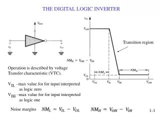
Gates (a) A transistor inverter. (b) A NAND gate. (c) A NOR gate.
Overview of Basic Logic Functions • Comparison function • Decoding function • Counting function • Arithmetic functions • Code conversion function • Encoding function • Data selection function • Data storage function
Overview of Basic Logic Functions • Comparison function • Compares two binary values and determines whether or not they are equal • Decoding function • Converts binary-coded information into a non-binary form • Counting function • Generates sequences of digital pulse that represent numbers
Overview of Basic Logic Functions • Arithmetic functions • Perform the basic arithmetic operations on two binary values: • Addition • Subtraction of two values • Multiplication • Division
Overview of Basic Logic Functions • Code conversion function • Converts, or translates, information from one code format to another. • Encoding function • Converts non-binary information into a binary code
Overview of Basic Logic Functions • Data selection function • Multiplexer (mux) • Switches digital data from any number of input sources to a single output line • Demultiplexer (demux) • switches digital data from a single input to any number of output lines
Overview of Basic Logic Functions • Data storage function • Retains binary data for a period of time • Flip-flops (bistable multvibrators) • Registers • Semiconductor memories • Magnetic-media memories • Optical-media memories
Fixed-Function Integrated Circuits IC package styles • Dual in-line package (DIP) • Small-outline IC (SOIC) • Flat pack (FP) • Plastic-leaded chip carrier (PLCC) • Leadless-ceramic chip carrier (LCCC)
Fixed-Function Integrated Circuits • Dual in-line package (DIP)
Fixed-Function Integrated Circuits • Small-outline IC (SOIC)
Fixed-Function Integrated Circuits • Flat pack (FP)
Fixed-Function Integrated Circuits • Plastic-leaded chip carrier (PLCC)
Fixed-Function Integrated Circuits • Leadless-ceramic chip carrier (LCCC)
Introduction to Programmable Logic • SPLD—Simple programmable logic devices • CPLD—Complex programmable logic devices • FPGA—Field-programmable gate arrays
Introduction to Programmable Logic • SPLD • PAL (programmable array logic) • GAL (generic array logic) • PLA (programmable logic array) • PROM (programmable read-only memory)
Test and Measurement Instruments • Analog Oscilloscope • Digital Oscilloscope • Logic Analyzer • Logic Probe, Pulser, and Current Probe • DC Power Supply • Function Generator • Digital Multimeter
Logic Gates • Inverter • AND Gate • OR Gate • Exclusive-OR Gate • NAND Gate • NOR Gate • Exclusive-NOR Gate
Truth table 0 = LOW1 = HIGH Boolean expression Pulsed waveforms The Inverter The output of an inverter is always the complement (opposite) of the input.
Boolean expression Truth table 0 = LOW1 = HIGH Pulsed waveforms The AND Gate The output of an AND gate is HIGH only when all inputs are HIGH.
3-Input AND Gate 4-Input AND Gate The AND Gate
Boolean expression Truth table 0 = LOW1 = HIGH Pulsed waveforms The OR Gate The output of an OR gate is HIGH whenever one or more inputs are HIGH
3-Input OR Gate 4-Input OR Gate The OR Gate
Boolean expression Truth table 0 = LOW1 = HIGH Pulsed waveforms The NAND Gate The output of a NAND gate is HIGH whenever one or more inputs are LOW.
3-Input NAND Gate 4-Input NAND Gate The NAND Gate
Boolean expression Truth table 0 = LOW1 = HIGH Pulsed waveforms The NOR Gate The output of a NOR gate is LOW whenever one or more inputs are HIGH.
3-Input NOR Gate 4-Input NOR Gate The NOR Gate
Boolean expression Truth table 0 = LOW1 = HIGH Pulsed waveforms Exclusive-OR Gate The output of an XOR gate is HIGH whenever the two inputs are different.
Boolean expression Truth table 0 = LOW1 = HIGH Pulsed waveforms Exclusive-NOR Gate The output of an XNOR gate is HIGH whenever the two inputs are identical.