Download

1 / 45
450 likes | 571 Vues
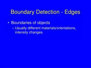
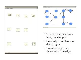
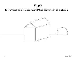
Hardware Feature Edges. Hardware Feature Edges. June 7, 2004 Morgan McGuire and John F. Hughes Brown University NPAR 2004. Goal. Find and stroke feature edges on the GPU. Feature Edges. Contour Front-face meets back-face Boundary Ridge Valley Silhouette Subset of contour

E N D
Hardware Feature Edges Hardware Feature Edges June 7, 2004 Morgan McGuire and John F. Hughes Brown University NPAR 2004
Goal Find and stroke feature edges on the GPU
Feature Edges • Contour • Front-face meets back-face • Boundary • Ridge • Valley • Silhouette • Subset of contour All defined by derivatives of normals… i.e. for nice polyhedra, adjacent face normals
n1 nA v1 nB n0 AB v0 v2 v3 Feature Tests eye eye = center of projection – v0 = depth complexity
Challenge GPU limitations: • No “Edge Processor” • No access to adjacency • No previous state for coherence • Cannot create or destroy edge geometry x Adjacency Vertex Processor Pixel Processor Rasterizer Vertices x Edges Triangles
Related Work • CPU Silhouettes • Exhaustive: Sutherland (circa ’77) • Randomized: Markosian et al. ’97 • Cutting sphere: Gooch ’99 • Dual space: Zorin and Hertzmann ’00 • GPU Silhouettes • G-Buffer: Saito and Takahashi ’90; McCool ’03 • Environment maps: Gooch ’99, Deitrich ’99 • Halo: Raskar ’01, ’02 • Pixel Processor + Readback: Brabec and Seidel ’03 • Edge vertices: Card & Mitchell ’02, Brennan ’03, Gooch ’03 • (None allow thick lines or brush strokes)
nA nB v1 AB v0 Vertex Attributes • GPUs allow 16 vertex “attributes” <position, normal, color, tex coords> • Can store other information… <position, face-normal A, face-normal B> • i.e. adjacent face normals The edge from v0 to v1 with adjacent faces A and B.
Agnosticism • The GPU doesn’t care • Attributes don’t have to be texture coords, colors • Face list doesn’t have to describe faces • Just has to have the right form • Face list: set of indices into vertex table • Vertex attributes: set of 4-vectors • e.g. store information about an EDGE of the model mesh: • In each VERTEX structure we send to the GPU • Call these “edge vertices”
nA nB v1 AB v0 Edge Vertices • Make a new mesh • Every edge becomes two vertices • <v0, nA, nB>, <v1, nA, nB> • Connected by a line • Use vertex processor to find vertices on contours • Hide non-contours when rendering • Degenerate polygons, a = 0, etc. • (nA eye > 0) xor (nB eye > 0)
Our Contribution Extend Edge Vertices with • More edge types • Ridge, Valley, Silhouette • Smooth Silhouette • Suggestive Contour • Brush strokes • Animation • Plan for Future Hardware
n1 nA v1 nB n0 AB v0 v2 v3 The Edge-Mesh • Every edge becomes four identical* vertices • Connected into a quadrilateral • Store adjacent vertices, not face normals Scalar texture parameter (i) = < v0, v1, v2, v3,n0,n1, r, i > 3D Vectors * Differentiated by i = {0, 1, 2, 3}
Rendering Test edges on the vertex processor • Feature Edge: • Extrude into a screen-space rectangle • Choose vertex position from i • Non-Feature Edge: • Hide beyond clipping plane • Early-out avoids rasterization overhead • Animation: • Animate v and n as a regular vertex and vertex-normal i=0 v0 i=3 i=1 v1 i=2
Thick quads leave visible gaps at joints Common problem (e.g. Raskar ’02) Thick Lines
p “outside” start cap m0 finish cap m1 s0 s1 quad “inside” Solution: End Caps • Computed in screen space • Follow projected normals m0, m1 • The only mutual information between adjacent edges!
Result No Caps Caps Works well for smooth objects…
Heuristic can Fail Vertex normals poorly reflect curvature for this object and our heuristic fails.
Heuristic can Fail Hidden Failures: Cap is on the wrong side, but the gap is inside the object.
Heuristic can Fail Visible Failure: Cap is on the wrong side and the gap is outside the object.
Analysis of Failure • Failure occurs when s is on the “concave” side of joint: • i.e. 2D curvature is negative • Probability of failure increases when: • Curvature is high and tessellation is low • Vertex normal represents curvature poorly e f
Screen vs. Object Space s0 = r s1 = r + L Good for animated low-poly models s = vx | vy Good for still and high-poly models Attached to vertices during animation
Applications “Zero CPU cycles were harmed in the rendering of the following images.”
Different Strokes Pen-Bot Crayon-Bot Bunny-Bot Blue Print-Bot Wispy-Bot
J. Lengyel’s Realistic Fur Algorithm • Shells • Stack 16 sparse textures • Perform extrusion in vertex shader • Looks like fur when viewed “head on” • Looks like 16 dots when viewed “side on” • Fins • Striped texture near CONTOURS • Looks like fur when viewed “side on” • We move this onto GPU • Anisotropic shading Images from Lengyel et. al, Real-Time Fur over Arbitrary Surfaces
Shadow Volumes • Find polyhedron bounding shadowed points • Any intersected surface is shadowed • Compute intersection via stencil operations • Caps • At the object and infinity • E. Lengyel implemented with GPU • Sides • Find CONTOUR edges • Extrude each one into a quad Light Cap Side Side Dark Cap (at infinity)
Zorin-Hertzmann Smooth Silhouettes f2= -0.1 n2 fA 0 v2 n1 A n0 v0 v1 B f1= -0.2 fB 0 f0= 0.8 Extend edge vertex to <v0, v1, v2, v3, n0, n1, n2, n3, r, i> Define an “above-water” function f = eye • n Either 0 or 2 edges have zero-crossings in f Estimate zero-crossing points A, B and connect them
A B DeCarlo et. al’s Suggestive Contours* • Smooth silhouettes with new above-water function • Only stroke when “ ” • i.e. • Pack k1, k2, t1, t2, n, v (x4, for a quad) into edge vertex
* Don’t try our S.C. method at home on GeForceFX… it is too hard to squeeze the curvature data into only 16 attributes! Just use DeCarlo’s image space algorithm, or…
GeForce 6800 GeForce 6800 and Radeon X800 support texture reads in the vertex processor. Commercially available by August. Pointers (stored in textures) cut redundant data. Using 16-bit pointers: Current: E = <v,v,v,v,n,n,r,i> x 4 = 304 bytes New: E = <ptr, i> x 4 + <#,#,#,#,r> = 14 bytes 20x improvement! (# is a pointer to a regular mesh vertex)
GeForce 7800? DirectX Next specification allows geometry to be created and destroyed– this eliminates the need for degenerate quads…
Follow-Up Jorn Loviscach extended our method to halos with MAX alpha blending and suggests a new curved silhouette algorithm.
Acknowledgements • Evasion Group, INRIA Rhone-Alpes • NVIDIA • Tomer Moscovich
n1 nA v1 nB n0 AB v0 v2 v3 Feature Expressions <v0, v1, v2, v3, n0, n1, r, i> nA = (v1 – v0) (v2 – v0) nB = (v3 – v0) (v1 – v0) eye = center of projection – v0 = depth complexity eye
Silhouettes 1. Set S := (S + 1) mod 255 2. If S == 0 then clear stencil buffer to 255 3. Render the model, setting stencil to S wherever the depth test passes 4. Set the stencil test to pass where stencil == S 5. Render contour edges