Download
1 / 18
180 likes | 322 Vues
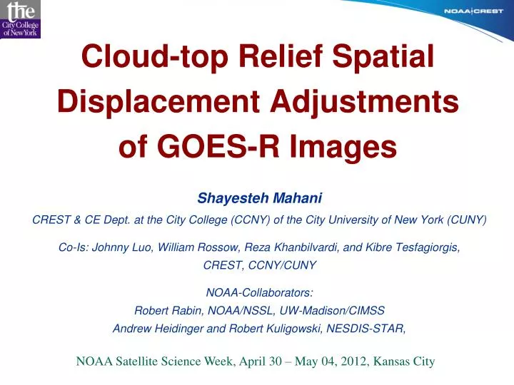
Cloud-top Relief Spatial Displacement Adjustments of GOES-R Images. Shayesteh Mahani CREST & CE Dept. at the City College (CCNY) of the City University of New York (CUNY) Co-Is: Johnny Luo , William Rossow, Reza Khanbilvardi, and Kibre Tesfagiorgis , CREST, CCNY/CUNY

E N D
Cloud-top Relief Spatial Displacement Adjustments of GOES-R Images Shayesteh Mahani CREST & CE Dept. at the City College (CCNY) of the City University of New York (CUNY) Co-Is: Johnny Luo, William Rossow, Reza Khanbilvardi, and KibreTesfagiorgis, CREST, CCNY/CUNY NOAA-Collaborators: Robert Rabin, NOAA/NSSL, UW-Madison/CIMSS Andrew Heidinger and Robert Kuligowski, NESDIS-STAR, NOAA Satellite Science Week, April 30 – May 04, 2012, Kansas City
Objectives • Estimate Cloud-Top Height (CTH) using 3-D principals and vertical height-temperature profile; • Enhance the quality of high resolution GOES-R infrared (IR) data by adjusting pixel based cloud-top relief Spatial Displacements (SD). Introduction Cloud VIS and IR images posses SD associated with CTH that is a function of satellite height, satellite-cloud view angle, sun zenith angle, and earth curvature. Stereo-graphical (3-D) principle using corresponding & simultaneous cloud IR data from GOES-E and -W, are applied to estimate CTH and its associated SD for adjustment. The 3-D based technique and the GOES-R Algorithm Theoretical Basis Document (ATBD) will be evaluated against CTH from CALIPSO as a reference to examine if the combined method can improve CTH output.
Major Tasks & Accomplishments • Derive the geometric relationship between cloud-top height and pixel-based spatial displacement for GOES-R (accomplished); • Derive the relationship between CTH, X-parallax of SD, and IR-CTBT, utilizing 3-D principals from scan-synchronous GOES-E and -W IR Images and optimize the parameters of the relationship using the SCE (Shuffled Complex Evolution) calibration Model to estimate CTH and adjust SD (90% accomplished); • Understand which IR channels, and/or combination(s) of which IR channels work better to estimate CTH and to adjust CTSD for a given cloud type, region, and season (Year-2); • Evaluate the CTH estimates and the CTH from GOES-R ATBD algorithm against the CALIPSO-CTH product (Year-2);
Major Tasks & Future Work • Modify/update the number and value of the optimized model parameters of the CTH-CTBT or CTBT-SD relationships for seasonal, topography, land type, and storm type variability, (Years-2 & 3); • Investigate improvement of CTH estimates by incorporating the proposed technique into ATBD model and evaluating the new CTH product against CALIPSO-CTH (Year-3); OUTLINE • Geometry of the relationship between CTH and pixel-based SD • Relationship between CTH and CTBT and CTH-based X-parallax, • Deriving the relationship between CTH, SD and IR-CTBT utilizing corresponding pairs of scan-synchronous and simultaneous GOES-E (13) and -W (11) as proxy for GOES-R Images. • Validation & Results.
Cloud-Top Height-Displacement Relationship S = (h, , ) g = Angular Displacement a = Angular Distance q h = Cloud-Top Height q = Satellite View Angle H = Satellite Height O' H C A Ly Lx g h B gf C N fB O B gl g l R B C' Lx a N B' dLx = R λ(rd) (km) dLy= R (rd) (km) S i(rd)= [hc (H+R) Sin(di)] /{R[(H+R) Cos(di) – (R+ hc)]} O Geometric Relationship between Cloud Top Height and its related SD. Cloud-Top Relief Spatial Displacement (BC or g)depends on Height of Cloud (h), Distance from Satellite (a) and Satellite Height (H).
Cloud Top Relief SD for GOES Images 50 45 40 35 30 25 20 15 10 5 0 h = 20 km h = 19 km h = 18 km h = 17 km h = 16 km h = 15 km h = 14 km h = 13 km h = 12 km h = 11 km h = 10 km h = 9 km h = 8 km h = 7 km h = 6 km h = 5 km h = 4 km h = 3 km h = 2 km h = 1 km Spatial Displacement (km) Cloud-Top Height (km) 0 5 10 15 20 25 30 35 40 45 50 55 60 65 Longitudinal or Latitudinal Distance from a Geostationary Satellite (Degrees) Relationship between Cloud Distance from Satellite, Cloud-Top Height and related Spatial Displacement
Stereoscopic Parallax Related to CTH GOES-W GOES-E dp is the X- or Stereoscopic Parallax Associated with hc, Cloud-Top Height, between GOES-E and -W Images of a Cloud Element. R = 6370 km (Radius of Earth)Hs = 36000 km IF: hc= 10 km dp = 16.0 km Hs (75W) (135W) hc dp Earth R 60° X C
Dependency of SD & CTH / BT 225 215 250 Latitude (Pixel numbers) 225 215 K 215 Latitude (Pixel numbers) 265 250 K 215 250 225K 265K 265 Longitude (Pixel Numbers) GOES-E (13) BT GOES-W (11) BT Comparison between x-parallaxes related to 2, cold (blue) and warm (red), temperatures between IR cloud-top BT of corresponding pairs of GOES-E (solid line) and GOES-W (dotted line) IR Images, over Southeastern U.S. (left) and Colorado (right). Longitude (Pixel Numbers)
RR X X Y X Y 10 20 30 10 20 30 40 50 Ground-Based Radar Rainfall Cloud-Top Relief Spatial Displacement GOES-W (135W) GOES-E (75W) hc hc Earth BTE BTW 10 20 30 10 20 30 10 20 30 40 50 10 20 30 40 50 GOES-E Cloud-Top Brightness Temperature GOES-W Cloud-Top Brightness Temperature (Pixel Size = 2 km)
Designing Fitted Piecewise Cloud-top BT-Height Relationship Line 6 parameters of a 3-pieces Linear Profile 3-Piece Line (6 Parameters) Designing a 3-pieces piecewise line with 6 parameters for Tb-Height/SD relationship. Optimized parameters are estimated based on minimizing X-parallax between a pair of simultaneous GOES-E and -W IR images using 3-D principle and Shuffled Complex Evolution algorithm (SCE-UA).
Cloud-Top Height (CTH) 2-D and 3-D Maps Estimated Cloud-Top Height Estimated cloud-top height and their related contours (right) in the forms of 2-D and 3-D maps. 3-D cloud-top height map CTH (km) Longitude (Degrees, West) Latitude (Degrees, North)
Cloud-top GOES-E & -W IR-BT Before and After Spatial Adjustment Original GOES-E (13) IR-BT Original GOES-W (11) IR-BT Spatial Adjusted GOES-E IR-BT Spatial Adjusted GOES-W IR-BT Cloud-top IR Brightness Temperature (K)
Difference of GOES-E and GOES-W IR-BT Before & After Spatial Adjustment Before Spatial Adjustment After Spatial Adjustment Latitude (Degrees, North) Latitude (Degrees, North) Longitude (Degrees, West) Longitude (Degrees, West) - 45 - 30 - 15 0 15 30 45 Difference Cloud-Top Brightness Temperature (Kelvin) Comparison between differences of GOES-E (13) and GOES-W (11) cloud-top BT before (left) and after (right) adjusting cloud-top relief spatial displacement.
GOES-W IR-BT vs. GOES-E Before and After Spatial Adjustment After Spatial Adjustment Before Spatial Adjustment GOES-W IR Brightness Temperature (K) GOES-W IR Brightness Temperature (K) Corr. = 0.987 RMSE = 2.45 Corr. = 0.95 RMSE = 4.65 GOES-E IR Brightness Temperature (K) GOES-E IR Brightness Temperature (K) Pixel based GOES-11 (-W) IR cloud-top BT versus GOES-13 (-E) IR before (left) and after (right) adjustment of cloud-top relief spatial displacement.
Cloud-top GOES-E & -W IR-BT Before and After Spatial Adjustment for Validation Original GOES-E (13) IR-BT Original GOES-W (11) IR-BT Cloud-top IR Brightness Temperature (K) Spatial Adjusted GOES-E IR-BT Spatial Adjusted GOES-W IR-BT
GOES-W IR-BT vs. GOES-E Before and After Spatial Adjustment, Validation After Spatial Adjustment Before Spatial Adjustment GOES-W IR Brightness Temperature (K) GOES-W IR Brightness Temperature (K) Corr. = 0.98 RMSE = 4.1 Corr. = 0.96 RMSE = 5.7 GOES-E IR Brightness Temperature (K) GOES-E IR Brightness Temperature (K) Pixel based GOES-11 (-W) IR cloud-top BT versus GOES-13 (-E) IR before (left) and after (right) adjustment of cloud-top relief spatial displacement using the derived CTH-IRBT for an independent study case, for validation.
Future Tasks • Evaluate the CTH estimates against CALIPSO-CTH (year 2); • Investigate if the piecewise line model can be enhanced by increasing the number of parameters (pieces of lines) (Year 2); • Test the model using other GOES thermal IR bands to investigate which IR frequency is more sensitive to cloud-top height, which will be used to improve CTH estimates (Year 2); • Investigate and enhance Comparing the CTH estimates with the CTH from GOES-R ATBD algorithm and the CALIPSO-CTH product (Year 2); • Investigate the impacts of seasonal, geographical, topography, storm types, and climate variability on model parameters and modify model for each (Year 3); • Incorporate the 3-D based model into GOES-R ATBD model and evaluate the new CTH product against CALIPSO-CTH (Year 3);