Download
1 / 23
230 likes | 230 Vues
This summary discusses the work of Justin Greenhalgh, Tim Hayler, and others in the T06O059-00-K LSC Meeting, LHO, March 2006. The analysis focuses on the impact of various modifications on a simple bolted structure, including changing the thickness of the top plate, modifying the bracing arrangement, and varying clamping methods. The results show that certain modifications did not significantly improve the structure's frequency. The conclusion suggests exploring alternatives such as introducing struts or damping systems to enhance performance.

E N D
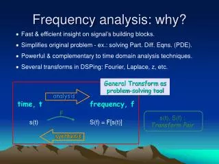
Frequency analysis of quad noise prototype Justin Greenhalgh summarising work of Tim Hayler and others in T060059-00-K LSC Meeting, LHO, March 2006 LIGO-G060107-00-K
Simple bolted structure Screws
Simple bolted structure – conclusions • Plenty of opportunity to vary the result with different representation of bolts/screws etc.
Asymmetric structure • Idea: outriggers on one side are at a better angle • Downside is that the outriggers at the other side are ineffective – not clear if the benefits will outweigh the disadvantages • Result – did not improve things 53Hz 52.5Hz
Change thickness of top plate • Extra stiffness and extra mass – did not help
Modify bracing arrangement and reduce mass of implementation ring • Reduce from three rings of bolts to one ring of bolts at implementation ring • But bolts not in the model, so not surprising this did not help the results • Modify bracing (outriggers) by looking at load paths and trying to straighten them • Probably we did not put enough mass into the outriggers – but even so it’s a surprise that it did not help at all • Bottom line result: • Before = 77.8 Hz • After = 77.8 Hz
Modify bracing arrangement and reduce mass of implementation ring
Varying the clamping method on the top plate case one. Fixed supports are maintained on the outriggers assembly pads to the implementation ring (implementation ring not included in model) and around the perimeter of the top plate. case two. Fixed supports are maintained on the outriggers assembly pads to the implementation ring (implementation ring not included in the model) and on the entire surface of the top plate.
Conclusions: Varying the style of clamping of the top plate does not make much difference So the plate is not “panting” to a significant effect Varying the style of the bolting model does not make much difference either Disappointing because these were obvious candidates for improving things Varying the clamping method on the top plate
Analysis of differences in CIT tests Typical CIT test configuration
Analysis of differences in CIT tests • Conclusion: • The side plates don’t change things nearly as much in the real world as the FEA suggests – so maybe it’s the way THEY are bolted that we should look at.
“X-brace” • Theory: • Create “hard points” at the tops of the X-braces. • X-braces extend the “triangles” idea used successfully in the top structure • Result: • No change in frequency • Maybe because the X-braces are not meaty enough compared to the side plates they are trying to stiffen
Struts • Break the envelope • But give good results • 50od 40id • ~1.8m long • 35 degrees to vertical
Removal of central side-plates • SIMPLE experiment, simply suppressed some parts of the structure • Improved primary beam modes by ~10 Hz • Modes were 77 & 86 Hz • Became 87 & 94 hz
Removal of central side-plates 87 Hz 77 Hz
Conclusions so far • Modelling bolts has the potential to build a model that matches the tests with a credible rationale • And hence making things better by use of modified bolted joints eg in compression/tension rather than shear. • Making the structure asymmetric did not help • Initial ideas did not help • Modify thickness of top plate, minor mods to outriggers • Reducing number of bolted joints in implementation ring may help • Need to figure out how to model bolted joints to assess this • Changes to clamping of top plate and modified bolting between side plates and top plate did not help • More radical change to outriggers (X-braces) did not help • But we think they will help if we trade mass into them • Struts outside the envelope helped a lot • But introduce internal modes of their own that would need fixing • This should only be a fallback • Removing the central plates helped ~10Hz • But introduces issues with assembly and potentially a big issue with welding
Options for the structure • Improve performance of structure • Tweaks to make better use of mass • Understand and then fix bolted joints • Strut to improve stiffness • Damping in control system • Electronic • Mechanical (strut or tuned-mass) • If we introduce a strut would we rather have better stiffness or better damping? (cannot do both) • And what about parasitic modes that come with the strut?