Download
1 / 46
460 likes | 594 Vues
US LHC Accelerator Research Program. BNL - FNAL- LBNL - SLAC. LARP Collimator Tasks. 6 October 2005 LARP Collaboration Meeting-St. Charles, IL Tom Markiewicz SLAC.

E N D
US LHC Accelerator Research Program BNL - FNAL- LBNL - SLAC LARP Collimator Tasks 6 October 2005 LARP Collaboration Meeting-St. Charles, IL Tom MarkiewiczSLAC
Four LARP Collimation Program Tasks:Address Efficiency, Reliability and Design of Phase I & Propose a possible solution for Phase II Conundrum • Use RHIC data to benchmark the code used to predict the cleaning efficiency of the LHC collimation system and develop and test algorithms for setting collimator gaps that can be applied at the LHC • Responsible: Angelika Drees, BNL [Task #2] • Understand and improve the design of the tertiary collimation system that protects the LHC final focusing magnets and experiments • Responsible: Nikolai Mokhov, FNAL [Task #3] • Study, design, prototype and test collimators that can be dropped into 32 reserved lattice locations as a part of the “Phase II Collimation Upgrade” required if the LHC is to reach its nominal 1E34 luminosity • Responsible: Tom Markiewicz, SLAC [Task #1] • Use the facilities and expertise available at BNL and FNAL to irradiate and then measure the properties of the materials that will be used for phase 1 and phase 2 collimator jaws [proposed new work package] • Responsable: Nick Simos, BNL [Task #4] Collimator Task Summary - T. Markiewicz
2005-06-01 DOE Review of Collimation Program: A+ • "The activity in collimation is impressive, with the work being approached in a very professional manner. It is a critical problem, and solving it will have great impact on the ability of the LHC to reach design luminosity. Even the task sheets for this project were done very professionally, lending confidence in a well-managed and well-focused activity. (The synergy with the ILC is clearly evident here.)" Collimator Task Summary - T. Markiewicz
Task 2: Use RHIC Data to Benchmark LHC Tracking Codes • Scope: • Install SixTrackwColl particle tracking code at BNL and configure it to simulate RHIC performance for both ions and protons. • Take systematic proton and ion data and compare observed beam loss with predictions • Test (and perhaps help to develop) algorithms proposed for the automatic set up of a large number of collimators • Resources Required: • 50% postdoc/student + supervision + travel • Timescale: • Now until LHC beam commissioning • Comments • Preliminary data taken; comparison programs being improved • Postdoc search ongoing Collimator Task Summary - T. Markiewicz
Task 2: Progress Since Pt. Jeff Meeting • Guillaume Robert-Demolaize from CERN visited BNL for 3 weeks after PAC. • ‘Special' loss proton data (1 h beam time, 2 times) taken at 100 GeV and in one ring only & loss maps with single collimators obtained. • The newest version of the SixTrack ("colltrack") code was copied over from CERN and compiles; modifications were made to implement the RHIC style collimators (dual plane, single sided). • A first pass on some simulations was made with a few hundred turns and a varying number of particles (up to a few thousands) and loss maps produced which were then compared with the data. However quantitative comparison was hindered by the necessary debugging required with the new code implementation. • Robert-Demolaize plans to continue to debug the RHIC simulation code at CERN and to produce simulated loss maps which will then be compared with the datasets. It is thought that these comparisons may begin in August or September after his other CERN responsibilities are addressed. Collimator Task Summary - T. Markiewicz
LARP Collaboration Fermilab Tertiary Collimators in IP1/IP5 Nikolai Mokhov, Fermilab LARP Collaboration Meeting Pheasant Run, St. Charles, IL October 5-6, 2005
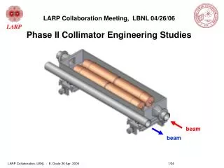
TERTIARY COLLIMATORS • Tertiary collimators at 8.4s around IR1/5 protect SC triplets from tertiary halo coming from particles leaking from 7s secondary collimators, upstream beam-gas and inefficiency of MPS if unsynchronized beam abort. • These TCTs must not induce peak energy deposition in the triplets above the quench limit (1.6mW/gm) with a safety margin of 3 nor induce detector backgrounds at level above IP produced backgrounds • 80 x 25 x 1000mm Cu jaws at .4s 145m from IP added to MARS15; Halo > 8.4s assumed to go as 1/r; operational beam loss rate at TCTV/H assumed to be 1E6 p/s Collimator Task Summary - T. Markiewicz
TERTIARY BEAM HALO LOSS IN IP5 Without TCTs With Cu TCTH, TCTV Collimator Task Summary - T. Markiewicz
MARS15 RESULTS FOR COPPER TCTs Peak power density is 0.35 mW/g in Q3. Particle fluxes on CMS similar to those from earlier studied accelerator backgrounds. Conclusion: keep TCT scraping rates below 2x10⁶ p/s. Collimator Task Summary - T. Markiewicz
TERTIARY COLLIMATORS PROGRESS & PLANS • MARS runs with & without TCTs; MARS runs with CU & W TCTs • File of TCT induced background rays sent to CMS • File of Beam1 loss in TCT region calculated by CERN 7 received 2005-09 • Need similar file for Beam2 • Need similar files for momentum cleaning insertion IR3 • Plan to begin updating results using these files beginning mid-October Collimator Task Summary - T. Markiewicz
US LHC Accelerator Research Program BNL - FNAL- LBNL - SLAC The LARP Collimation Program TASK 4 Summary Material Irradiation Studies Nick Simos Nikolai Mokhov
Task #4: Irradiation Damage Assessment of LHC collimator materials • Scope: • Irradiate 2-D weave carbon-carbon and exact graphite used in Phase I jaws plus materials considered viable for Phase II jaws • BNL AGS/BLIP (117 & 200 MeV protons) • FNAL120 GeV protons behind pbar target planned • Measure material properties: thermal expansion, mechanical properties, thermal conductivity/diffusivity and thermal shock • BNL Hot Cell Sample Measurement Facility • Resources Required: • Irradiation & hot cell use fees • Sample prep, measurement apparatus improvement • Fraction of postdoc + fraction of physicist + travel • Timescale: • 2005,2006 proton runs + analysis into FY2007 • Status: • Phase I Carbon-Carbon irradiation completed • Sample activation measurements completed • Thermal Expansion of specimens started • PLANNING of FY06 Post-Irradiation and Follow-up Irradiation Studies Collimator Task Summary - T. Markiewicz
C-C samples arrive from CERN supplier and are assembled and pre-tested before irradiation Collimator Task Summary - T. Markiewicz
LHC Phase I 2D carbon-carbon samples Irradiated at BNL, Disassembled, Inspected & Dose/sample measured Beam Spot during the short 200 MeV Irradiation at the end of the cycle Integrated 2D carbon Exposure: micro-Amp Hours > 100,000 Preliminary Assessment: 2D CC specimens normal to the planes of reinforcing fibers and close to the center of the beam (receiving high dose) experienced degradation. Less degradation was seen in the specimens along the reinforcement. NOTE: Total dose received MUCH HIGHER than what LHC collimator jaws will see. Collimator Task Summary - T. Markiewicz
LHC Phase I and Phase II Planned Activities • Irradiation Damage Assessment of 2D Carbon of Phase I: • Using the nickel foils of the irradiation assembly and deduce exact beam position and profile through • radiographic analysis. These results, combined with the exposure record will provide the number of • protons seen by the different specimens. • USE results for irradiation damage (dpa) estimation. • Refine model for dpa estimation (based on MCNPX code and damage cross-sections) • Isotope generation: • The isotopes generated in the composite will be fully assessed. • Preliminary results show that the predominant is Be-7. Such result is important for collimator servicing. • CTE set-up for 250 C thermal Cycling: • Thermal expansion measurements with cyclic temperature profile between room temperature • and 250 degrees C (as requested by LHC collimator group. • Measure effects of irradiation on the coefficient of thermal expansion (CTE). • Upgrade Apparatus to Measure Irradiation Effects on: • Thermal Condutivity/Diffusivity • Electrical Resistivity • PLAN and Conduct New Irradiation Experiments that include Phase II Materials: • - Irradiate At BNL BLIP candidate materials of Phase II (copper, superInvar, Inconel, 3D CC, etc.) • - Irradiate at FNAL at the Pbar target area using much higher energy protons and assess irradiation damage • as well as damage dependence on proton energies Collimator Task Summary - T. Markiewicz
Irradiation Tests at FNAL Pbar Target Area PRELIMINARY Layout for FNAL Pbar Target Irradiation Proposed Target Stack Beam time “free” but need to hire/pay for technician Collimator Task Summary - T. Markiewicz
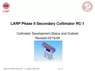
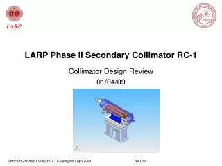
Task#1: Studies of a Rotatable Metallic Collimator for Possible Use in LHC Phase II Collimation System • If we ALLOW (rare) ASYNCH. BEAM ABORTS to DAMAGE METAL JAWS, is it possible to build a ROTATING COLLIMATOR • that we can cool to ~<10kW, keeping T<TFRACTURE and PH2O<1 atm. • that has reasonable collimation system efficiency • that satisfies mechanical space & 25um accuracy requirements • Scope: • Tracking studies to understand efficiency and loss maps of any proposed configuration (SixTrack) • Energy deposition studies to understand heat load under defined “normal” conditions & damage extent in accident (FLUKA & MARS) • Engineering studies for cooling & deformation • Construct 2 prototypes with eventual beam test at LHC in 2008 • After technical choice by CERN, engineering support • Commissioning support after installation by CERN Collimator Task Summary - T. Markiewicz
Status of Phase II Collimator Conceptual Designat 2005-06-01 DOE Review • Adequate software in place and MANY studies have been done but … • We do NOT yet have a conceptual design for the 1st of the 11 collimators needed (per beam) in IR7 • 28 of 30 Phase II collimators will not have a heating problem • No magic design or material which could simultaneously provide good efficiency with combination of energy absorption, thermal conductivity, & thermal expansion to maintain 25 um flatness tolerance over length of jaw during 1hr/12min (90/450kW) beam lifetime transients for nominal jaw length (1m) and gap setting (7s) • Focus on • 150mm O.D. 25mm wall Cu jaws with helical cooling tubes • 150mm O.D. “solid” Cu jaws cooled with axial flow over 36° of arc Collimator Task Summary - T. Markiewicz
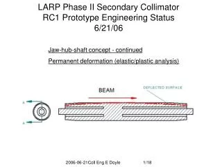
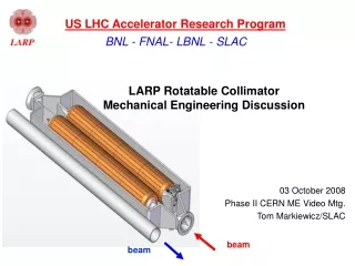
beam water Limited cooling arc: free wheeling distributor – orientation controlled by gravity – directs flow to beam-side axial channels. Pro: Far side not cooled, reducing DT and thermal distortion. Con: peak temperature higher; no positive control over flow distributor (could jam); difficult fabrication. 360o cooling by means of helical (or axial) channels. Pro: Lowers peak temperatures. Con: by cooling back side of jaw, increases net DT through the jaw, and therefore thermal distortion; axial flow wastes cooling capacity on back side of jaw. Helical and axial cooling channels Collimator Task Summary - T. Markiewicz
ANSYS thermal and structural results for full ID cooling and limited cooling arc showing 64% less distortion with limited cooling 360° cooling of I.D. 36° cooling arc Note transverse gradient causes bending Note axial gradient 61C 89C Note more swelling than bending support dx=221 mm Spec: 25mm dx=79 mm 64% less distortion support Collimator Task Summary - T. Markiewicz
Material evaluations Collimator Task Summary - T. Markiewicz
Directions under investigation & negotiation at time of 2005-06-01 DOE Review • Redefine secondary hybrid system to treat 1st collimator as special • Break 1st secondary into two (unequal?) lengths of perhaps different materials • Grooved “expansion slots” to limit deformation • Adjust gaps of the first carbon & metal secondary to reduce heat load while maintaining efficiency with remainder of secondary system • Keep 1st C-C secondary collimator’s jaws at 7s and leave out 1st metal secondary collimator • Relax deformation tolerance relaxed to if jaws expand AWAY from beam • Begin to deal with LHC infrastructure & operational constraints • 45mm jaw gap at injection incompatible with NLC inspired circumferentially mounted gap adjustor • Look into adopting Phase I adjustment mechanism • Spatial constraints of LHC beam pipes & tunnel a challenge • Jaw dimensions, tank dimension Collimator Task Summary - T. Markiewicz
IR7 Collimator Layout Primary Collimators Beam Direction Hard Hit Secondary Collimators Collimator Task Summary - T. Markiewicz
Possible Path to Immediate RC1 Prototype: Leave TCS#1 Carbon-Carbon, Remainder Cu Collimator Task Summary - T. Markiewicz
beam beam Mechanical Model 2005-06-01 Used NLC Concept of Central Strongback with mid-collimator jaw gap adjuster Collimator Task Summary - T. Markiewicz
June 15-17 CERN/SLAC Collaboration Meeting • Attendees • CERN: Ralph Assmann (Project Leader, Tracking), Allesandro Bertarelli (Mechanical Eng.), Markus Brugger (Radiation Issues), Mario Santana (FLUKA) • SLAC: Tom Markiewicz, Eric Doyle (ME), Lew Keller (FLUKA), Yunhai Cai (Tracking), Tor Raubenheimer • Radiation Physics Group: Alberto Fasso, Heinz Vincke • Results • Agreement on basic design of RC1 (1st rotatable prototype) • Transfer of many of CERN mechanical CAD files • Lists of • Further studies required • Outstanding Engineering Issues requiring more design work • Project Milestone List & Action Items List • Test Installation of “New FLUKA” Collimator Task Summary - T. Markiewicz
Conceptual Design of RC1 (1 of 2) • Mechanics must fit within CERN Phase I C-C envelope • 224mm center-to-center with 88mm OD beampipes • 1480mm longitudinal flange-to-flange • 25mm adjustment/jaw (22.5mm relative to beam w/±5mm allowed beam center motion • and use Phase I alignment and adjustment scheme • Two 75cm Cu cylindrical jaws with 10cm tapered ends, 95cm overall length with axes connected to vertical mover shafts • 136mm OD with 9mm taper • Each jaw end independently moved in 10um steps • Vacuum vessel sized to provide 8mm clearance to adjacent beam and allow gross/fine 0°, 45°, 90° positions • Relaxed mechanical deformation specifications • <25 um INTO beam guaranteed by adjustable mechanical stop(s) • Ride on groove deep enough to not be damaged in accident case • Adjustable between ±5 and ±15 sigma (2-6mm) & centered on beam • <325 um (750um) AWAY FROM beam @ 0.8E1p/s loss (4E11p/s) • Flexible support on adjustment Collimator Task Summary - T. Markiewicz
Conceptual Design of RC1 (2 of 2) • Assumed worst case heat load (FLUKA) • 11.3 kW/jaw steady state, 56.5kW/jaw transient (10 sec) • Cooling boundary conditions • 200 °C maximum temperature of Cu • 27 °C input H2O temperature • 42 °C maximum allowed return H2O temperature • Two Cooling Schemes under consideration • Helical tube: more secure H2O-vacuum interface • Axial channels w/ diverter: superior thermal mechanical performance • Sufficient pressure (3 atm.) to prevent local boiling in transient • Flexible supply lines to provide 360° rotation • Other • Vacuum: <1E-7 Pa (1.3E-5 torr) • RF: shielding scheme has been proposed Collimator Task Summary - T. Markiewicz
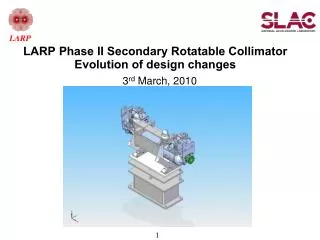
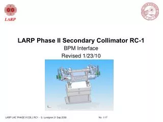
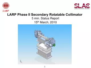
Proposed layout: 136mm diameter x 950mm long jaws, vacuum tank, jaw support mechanism and support base derived from CERN Phase I Collimator Task Summary - T. Markiewicz
Vacuum tank enlarged to accommodate jaw motion. Relative location of opposing beam pipe – near interference in skew orientations 10° deviation Collimator Task Summary - T. Markiewicz
Helical cooling passages – fabrication concept Based on CERN’s design – no weld or braze between water & vacuum • Tube formed as helix, slightly smaller O.D. than jaw I.D. • O.D. of helix wrapped with braze metal shim • Helix inserted into bore, two ends twisted wrt each other to expand, ensure contact • Fixture (not shown) holds twist during heat cycle • Variations: • Pitch may vary with length to concentrate cooling • Two parallel helixes to double flow • Spacer between coils adds thermal mass, strength • Electroform jaw body onto coil Collimator Task Summary - T. Markiewicz
Adjustable central gap-defining stop • Stop prevents gap closing as jaw bows inward due to heat • Jaw ends spring-loaded to the table assemby … move outward in response to bowing • May use two stops to control tilt • Slot deep enough to avoid damage in accident • Stop far enough from beam to never be damaged & is out of way at injection Collimator Task Summary - T. Markiewicz
Flexible end supports used in conjunction with central gap-defining mechanism Adjustable central jaw stops (not shown) define gap Flexible bearing supports allow jaw thermal distortion away from beam Self aligning bearing Leaf springs allow jaw end motion up to 1mm away from beam CERN’s jaw support/positioning mechanism. Vacuum tank, bellows, steppers not shown. Collimator Task Summary - T. Markiewicz
Spring loaded fingers ground two jaws through range of motion Rigid round-square transition Jaw support & gap adjustment borrowed from CERN RF Contact Overview Collimator Task Summary - T. Markiewicz
Clearance problems with RF contacts Jaw Support Concept – unresolved issues interferences with RF parts Collimator Task Summary - T. Markiewicz
Unresolved interferences between RF parts and cooling and support parts Jaw rotation mechanism not devised Substantial forces to rotate jaw Mandrel to support coil not shown CERN design: Jaw supported on individually moveable shaft at each end, controlled by steppers external to tank. Bellows allows full range of jaw motion Continuous one-piece cooling tube brazed to jaw, exits tank at each end through shaft. Flex cooling supply tube concept Collimator Task Summary - T. Markiewicz
Detail of flex cooling supply tube Stub-shaft (bearing not shown) Contiguous with helical tube inside jaw. Formed after assembly-brazing of jaw and installation of bearing on stub-shaft Exits through support shaft per CERN design Material: CuNi10Fe1, 10mm O.D., 8mm I.D. Support shaft Collimator Task Summary - T. Markiewicz
Final Expected Performance of RC1 Design Collimator Task Summary - T. Markiewicz
Outstanding RC1 Unresolved Issues • Jaw positioning • Acceptance of estimated deflection by CERN:281/869um • Design concept for central stop: gap adjust, 5 central position float,.. • Bearings & springs attaching jaws to vertical movers • Load capacity of steppers • Jaw alignment perpendicular to collimation direction • Jaw rotation • Specification of mechanism on crowded jaw • Force required to rotate jaws against cooling coil • Misc • Spring arrangement for H, V, S orientations • Springs to ensure that device fails open • Motors, cables, temperature sensors, position probes, … • Cooling • Possible local boiling in transient condition & need for P~3 atm. H2O system • More flexible yet vacuum safe water supply for helical cooling • Vacuum safe water connection/diverter for axial cooling scheme Collimator Task Summary - T. Markiewicz
Other Studies Planned • Tracking Studies: Hit maps for each of 11 IR7 collimators/beam and efficiency with 60cm C-C primaries and Cylindrical 75cm jaws which includes effect of tertiary collimators and absorbers • FLUKA energy deposition with 60cm primaries & cylindrical 75 cm jaws Complete self consistent package of tracking, FLUKA & ANSYS results to support design choices unambiguously • Better definition of RC1 thermal tests • Remnant & Prompt Dose Rate calculations • Engineer damage assessment mechanism into design • Thermal shock studies • Studies/experiments to verify • assumed extent of damage in accident: assume 1mm for now • Where metal slag will wind up • acceptable peak temperature of jaw: assume 200 °C for now Collimator Task Summary - T. Markiewicz
FY2005 Deliverables RC1 CDR Draft 9/30/05 32 pages + figures Collimator Assembly & Test Area (SLAC-ESB) Collimator Task Summary - T. Markiewicz
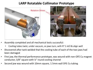
FY2006 Work PlanNon-beam Mechanical & Thermal Performance of RC1 • Single jaw thermal test: one jaw with internal helical cooling channels to be thermally loaded for testing the cooling effectiveness and measuring thermal deformations. • Heating by commercial electric resistance heaters coupled to the jaw with thermal grease • Operated in a tank purged with inert gas to protect the copper jaw from oxidation. • Flexible cooling supply that won’t be intended to allow rotation of the jaw. • A FE model of the test jaw will be used as a benchmark to evaluate the response of the test jaw to the test conditions. • Full RC1 prototype: a working prototype for bench top testing of the jaw positioning mechanism, supported to simulate operation in all necessary orientations, but not intended for mounting on actual beamline supports with actual beamline, cooling, control and instrumentation connections. • Lidded vacuum tank for easy access. • Cooling water feed-throughs and flexible connections as realistic as possible. • A reasonable effort will be made to test RC1 under heat loading but this will probably prove to be impractical. Collimator Task Summary - T. Markiewicz
FY 2006 Deliverables • Final version of RC1 CDR • Nov. 1, 2005 ? • External review of RC1 CDR • Nov. 14-18, 2005 ? • Dec 12-17, 2005 ? • Performance report on RC1 • Sept.30, 2006 Collimator Task Summary - T. Markiewicz
Inter-Lab Collaboration • Excellent good will & cooperation limited only by busy work loads on other systems • Exchange of mechanical drawing files • Installation of latest FLUKA at SLAC • Transfer of latest mod to SixTrack • Latest hit maps with 60cm primaries • Invaluable 3 day visit by 4 CERN staff • Monthly video meetings mostly killed April-present due to visit, other meetings, summer, … • Next video meeting Oct 11, 2005 • CERN review of SLAC draft CDR • CERN participation in RC1 CDR review • Exchange of detailed technical information will be crucial to delivering prototypes on time • Drawing of support structures for H, V Skew • Ideally, CERN would send old prototype parts (i.e. everything [support structure with steppers, motors, bellows, LVDTs,…] except for the tank & cylinder jaws) rather than have SLAC re-fab from drawings or from transcriptions of drawings Collimator Task Summary - T. Markiewicz
Task 1 Conclusions • To meet the Jan.1, 2008 RC2 ship date requirement SLAC and CERN collaborators have agreed on an initial set of specifications for the first mechanical prototype RC1 • based on extensive but incomplete studies done to date • consistent with CERN beam & mechanical constraints & which uses Phase I design to maximum extent • RC1 Prototype Conceptual Design, while not 100% complete, has been written up and serves as a start point for construction. • report to be finalized & reviewed in FY2006 • Fabrication of RC1 in two main steps in FY2006, with appropriate thermal mechanical tests, should validate most of the design issues • Design extension to RC2, a beam-test-capable prototype, will occur in parallel • Good (but of course could always be better) communication and exchange of information marks collaboration between labs • 100% devoted manpower required to ensure success Collimator Task Summary - T. Markiewicz
Action Items from Session • Tertiary Collimators • Prepare a better defined schedule of required inputs from CERN and delivered results from MARS team • Radiation Studies • Specify when results of first irradiation cycle will be ready • Understand financial requirements of both continued BNL program and expansion of effort to Fermilab 120 GeV area • Crystal Collimation • Develop a proposal LARP sponsored R&D required to incorporate crystal collimation into LHC: where, when, etc. • Rotatable Secondary Collimator Prototypes • Continue work on lists shown at session Collimator Task Summary - T. Markiewicz