Download
1 / 18
180 likes | 297 Vues
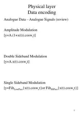
CS3502, Data and Computer Networks: the physical layer-4. Synchronization. to transport bits from X to R , R must know when X is transmitting, in order to correctly interpret the signals; 2 standard ways are synchronous and asynchronous . asynchronous transmission

E N D
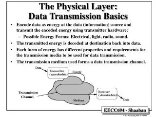
Synchronization • to transport bits from Xto R, Rmust know when X is transmitting, in order to correctly interpret the signals; 2 standard ways are synchronous and asynchronous. • asynchronous transmission • small groups of bits (5-10 bits) • each small group synchronized separately • simple signaling (NRZ) • short distances only; eg, PC to printer • start and stop bits mark the bit group • how much overhead? how efficient is this?
synchronization • synchronous transmission • start, end of data marked by flag byte (01111110) • flag pattern must not appear inside frame; bit-stuffing takes care of this • encoding -> need self clocking codes • exercise: give a FSM for bit stuffing for the flag 01110, and to unstuff bits at the receiver • what is the overhead (efficiency)?
interfacing • this means translating from 1 physical protocol to another • digital devices usually have a very limited data transmission/reception capability - not able to transmit onto a network directly • examples: • digital to analog (modems) • digital to digital (PC to LAN) • 4 parts of standard interface: • mechanical • electrical • functional • procedural
interfacing : EIA -232 standard • terminology • DTE- data terminal equipment -the device which we wish to connect to the network • generic term for data source, data terminal (sink), or both • examples: PC, computer terminal, workstation • DCE - data circuit terminating equipment - the device which interfaces with the network • creates, maintains and terminates connection with network • signal conversion and coding • example: modem
interfacing : EIA -232 standard • 25 pin connector; most apps. don’t use all • signal/line types: data, control, timing, ground. (note Table 5.1 list) • 15 meters max distance • +3 to +25 volts for 0; -3 to -25 V for 1. • unbalanced/asymmetric connection (circuit completed by ground). • 1 data line each way, so full duplex possible • more details in text;Tanenbaum p114.
interfacing : ISDN physical connector • standard for ISDN connections (Integrated Services Digital Network) • ISDN basic data rate: 144 Kbps • symmetric - this gives better electrical properties • more logic, less circuits: 8 pins • 2 data pins each way = 4 data pins • date circuits carry both data and control information • other pins for power sources
multiplexing problem: a transmission line operates at 1.544 Mbps, but 1 connection needs only 64 Kbps; so rest is wasted.... since 1.544 Mbps costs about $2K/ month. solution: share the link among many users, each paying only their part. purpose: to utilize as much of the line as possible 3 techniques: FDM, synch TDM, statistical TDM
multiplexing : FDM • analog signals with high bandwidth • TV Cable channels; broadcast radio; voice trunks * • must have Wlink>wi i.e.,link capacity greater than sum of channels. • main carrier is a composite of many subcarriers. each subcarrier may be modulated with 1 channel • example: a carrier has a total bandwidth of 240 MHz, from 54 to 294 MHz. Subcarriers are centered every 6 MHz; each forming 1 channel. • guard band necessary to avoid interference
multiplexing : FDM • FDM problems • crosstalk - can occur between neighboring channels, if overlap too close • intermodulation noise - possible on high capacity links over distance • noise, clarity - over distance, analog signals more vulnerable than digital; gradually being replaced in most areas. • switching - not as efficient with analog signals
multiplexing : TDM • two types: synchronous and statistical • synchronous TDM • digital data • signal - usually digital; can be analog signal coded digitally • data rate of link must be greater than sum of inputs • similar to timesharing computers • example: T1 multiplexer • standards: DS0, DS1 (T1), DS3 (T3); OCn; EC1
multiplexing : TDM • synchronous TDM • time slot to each input line • 1 slot for synchronization • unused time slots lost • slot size 1 bit or 1 byte, in general • physical layer; no error or flow control • Q: how much buffer space needed? • Q: what capacity needed for 24 voice channels? how many voice channels possible on a T3 line? OC3? OC12? how many T1 lines on an OC12? OC48?
statistical TDM • another way of assigning time slots • if input rates irregular, varied, synch TDM could be wasteful; stat. TDM could be more efficient • slots are assigned dynamically, as needed; • requires more intelligence; more of a data link layer function • frames must have more control information; • show fields of a possible frame • more overhead than synch. TDM; closer to a MAC type protocol
comparison: stat and synch TDM • synch TDM • fixed number slots per round • can waste slots • timing simpler, fixed • format simpler • stat TDM • variable number slots per frame • doesn’t waste slots • more overhead, complexity; similar to data link function • Q: how much buffer space needed for stat TDM?
stat TDM - buffer space summary • average input rate must be less than link capacity ; but may exceed temporarily. • buffer space stores temporary overflows • buffer size must be estimated based on expected input rates and their arrival distribution. Given these we can calculate buffer size (queue length); but in reality never can be completely sure. • link utilization is given by a standard queueing formula • as approaches 1, queue (buffer) size becomes very large, quickly; approaching infinity as reaches or exceeds 1 • utilization of no more that 0.8 is good rule of thumb
the voice channel and telephone system • basic telephone network designed to deliver quality voice service; • voice emits analog signal - sound waves - from 30 to 10,000 Hz. Human ears detect up to 20K Hz. • most energy in 200-3500 Hz range; Standard analog voice channel is 4000 Hz. This key number selected many years ago by phone company. • standard PCM digital voice channel is 64 Kbps. • most local telephone loops still analog • all long distance in US is digital; majority is fiber.
the voice channel and telephone system • voice not very sensitive to most noise and distortion; for this and other reasons, local telco loops not well suited to modern data networks • However, the local telco networks are one of few comm. links between homes, businesses and rest of the world • Structure of U S Telephone networks /companies • local loops “last mile” and telcos • long distance networks and companies • network equipment
video channels and the cable TV system • TV cable system established only recent decades • switching equipment designed for broadcast TV • standard TV - needs 6 MHz per channel • copper coaxial cables capable of ~500 MHz; carry many TV channels. • these cables have capacity to carry thousands of voice channels and/or high speed data -- but need appropriate switching equipment at home office, and in homes • already becoming a reality . Will threaten existence of old telcos. (note pending merger of ATT, TCI)