Download

1 / 25
260 likes | 530 Vues
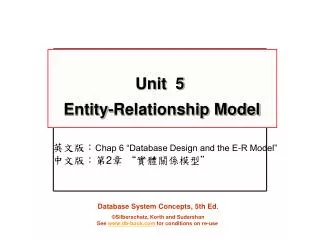
Chapter 3: The E-R Diagram. Modeling Reality. A database must mirror the real world if it is to answer questions about the real world Data Modeling is a design technique for capturing reality. STUDENT. Social_Security_No Name Major. The Conceptual Model (ER diagram).

E N D
Modeling Reality • A database must mirror the real world if it is to answer questions about the real world • Data Modelingis a design technique for capturing reality STUDENT Social_Security_No Name Major
The Conceptual Model (ER diagram) • representation of structure and constraints of database independent of software • Mainstream approach to conceptual modeling is ERD • ease of use • CASE support • entities and relationships are “natural” • No standard notation • Building blocks are entities, attributes, relationships, and identifiers
Elements of an ER diagram ASSOCIATIVE ENTITY ENTITY WEAK ENTITY ATTRIBUTE MULTIVALUED ATTRIBUTE DERIVED ATTRIBUTE RELATIONSHIP INDENTIFYING RELATIONSHIP
0010 Scott George 56 Neat Street Boulder, Colorado 35882-2799 507-293-8749 CUSTOMER An Entity • Something of interest in the environment (e.g., person, place, object, event, concept) • Represented in E-R diagram by a rectangle • An instance is a particular occurrence of an entity Entity An Instance of the Customer Entity
Entities • Entity Type - a collection of entity instances that share common properties (also simply called an Entity) • Entity Instance - an individual occurrence of an entity type • Strong Entity - exists independently • Weak Entity - depends on existence of another entity to have significance • ex.: EMPLOYEE (strong) has DEPENDENT (weak)
An Attribute • A discrete data element • Describes an entity (i.e., is a characteristic) • Meaningful (for the system being modeled) • Attributes are the items of interest to the organization -- the things being stored CUSTOMER This Customer entity has eight attributes Customer_Number Last_Name First_Name Address City State Zip Phone
Types of Attributes • Simple - at the atomic, most basic level • Composite - a related group of attributes • ex: address (street, city, state, zip) • Single Valued - only one value per entity instance (e.g., last name, date of birth) • Multivalued - multiple values per entity instance (e.g., degrees, clubs, skills) • Identifier - an attribute that uniquely identifies each entity instance (e.g., Social Security Number)
Identifiers • Every instance of an entity must be uniquely identified (to unambiguously distinguish them) • An identifier can be one or more attributes (e.g., first name, middle name, and last name) • Create an identifier if there is no obvious identifying attribute (e.g., part number) • Underline identifiers in diagrams
Identifiers • Criteria for Selecting Identifiers • Will not change in value. • Will not be null. • No intelligent identifiers • Substitute new, simple keys for long, composite keys.
Relationships • A relationship is an association between the instances of one or more entities • The degree of a relationship indicates the number of entities involved • The cardinality of a relationship describes the number of instances of one entity associated with another entity
Relationship degree Binary Unary Ternary
Relationship Cardinality • Cardinality Constraints - the number of instances of one entity that can or must be associated with each instance of another entity. Minimum Cardinality • If zero, then optional. • Maximum Cardinality • Mandatory One - when min & max both = 1.
Relationship cardinality notation Mandatory one Mandatory many Optional one Optional many
Complex Relationships • Attributes of Relationships • Associative Entities (Gerunds) • All relationships involved are “many” • Result has independent meaning • Gerund has one or more non-key attributes INSTRUCTOR COURSE Teaches
Instead…. INSTRUCTOR COURSE SECTION
Relationships • Modeling Time-Dependent Data • Time Stamps • Multiple Relationship - more than one relationship between the same entity types
Hierarchical Relationships • Occur frequently • Model as multiple 1:M relationships DIVISION FIRM DEPT
Different notation CUSTOMER * Customer ID Customer name ORDER * Order ID Order Date
Third style of notation Customer ID Customer name CUSTOMER 1 SUBMITS M Order ID Order date ORDER
Oracle notation CUSTOMER #Customer_ID * Customer Name ORDER #Order_ID * Order Date
Identifier Attribute Cust_ID Last_Name First_Name Address City ST Zip 0001 Snerd Mortimer General Delivery Tampa FL 33647 0002 Fogg Bob 567 Fogg Lane Omaha NE 32405 0003 Amos Famous 2 Cookie Ct. Miami FL 33133 0004 Targa Maxine 67 Fast Lane Clinton NJ 20082 0005 George Scott 56 Neat St. Boulder CO 35882 0006 Guy Nice 290 Pleasant St. Tampa FL 33641 0007 Smith Bob 76 Quaker Path Wynn NY 21118 0009 Smith James 234 Bayview Tampa FL 33641 Example Entity & Instances
Entity Type versus System Input, Output, or User What’s wrong with this picture? TREASURER EXPENSE REPORT GIVES TO MANAGES SUMMARIZES ACCOUNT EXPENSE HAS