Download
1 / 25
300 likes | 567 Vues
Signal Encoding Techniques. Raj Jain Washington University Saint Louis, MO 63131 Jain@cse.wustl.edu These slides are available on-line at: http://www.cse.wustl.edu/~jain/cse473-05/. Coding Terminology and Design issues Digital Data, Digital Signal: AMI, Manchester, etc.

E N D
Signal Encoding Techniques Raj Jain Washington UniversitySaint Louis, MO 63131Jain@cse.wustl.edu These slides are available on-line at: http://www.cse.wustl.edu/~jain/cse473-05/
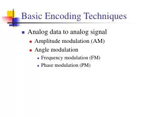
Coding Terminology and Design issues • Digital Data, Digital Signal: AMI, Manchester, etc. • Digital Data, Analog Signals: ASK, FSK, PSK, QAM • Analog Data, Digital Signals: PCM, Companding • Analog Data, Analog Signals: AM, FM Overview
Coding Terminology Pulse • Signal element: Pulse (of constant amplitude, frequency, phase) • Unipolar: All positive or All negative voltage • Bipolar: Positive and negative voltage • Mark/Space: 1 or 0 • Modulation Rate: 1/Duration of the smallest element =Baud rate • Data Rate: Bits per second • Data Rate = Fn(Bandwidth, signal/noise ratio, encoding) +5V 0 -5V +5V 0 -5V Bit
Bits 0 1 0 0 0 1 1 1 0 0 0 0 0 NRZ Clock Manchester NRZI Coding Design +5V 0 -5V • Pulse width indeterminate: Clocking • DC, Baseline wander • No line state information • No error detection/protection • No control signals • High data rate • Polarity mix-up Þ Differential (compare polarity)
Clock Recovery Circuit Received Signal t d/dt Pre Filter t Squarer t Phase LockLoop Clock t
Digital Signal Encoding Formats • Return-to-Zero (RZ)0 = Remain at zero, 1 = +ve for ½ bit duration • Nonreturn-to-Zero-Level (NRZ-L) 0 = high level, 1 = low level • Nonreturn to Zero Inverted (NRZI) 0 = no transition at beginning of interval (bit time) 1 = transition at beginning of interval RZ
Multi-level Binary Encoding • No loss of sync with 1’s • zeros are a problem • No net dc component • Error detectionNoise Þ violation • Two bits/Hz • 3 dB higher S/N • 2b/Hz. Not 3.16 b/Hz • Bipolar-AMI: 0 = no line signal 1= +ve or -ve for successive 1’s • Pseudo-ternary:0 = +ve or -ve for successive 0’s 1= no line signal No advantage over AMI
Bi-phase • Manchester: Used in Ethernet0 = High to low transition in middle 1 = Low to high transition in middle • Differential Manchester: Used in Token RingAlways a transition in middle 0 = transition at beginning 1= no transition at beginning • No DC • Clock sync • Error detection • 1 bit/Hz, • baud rate = 2 bit rate
Scrambling • Bipolar with 8-Zero Substitution (B8ZS):Same as AMI, except eight 0’s replaced w two code violations 0000 0000 = 000V 10V1 • High Density Bi-polar w 3 Zeros (HDB3): Same as AMI, except that four 0’s replaced with one code violation 0000 = 000V if odd number of ones since last substitution 100V otherwise
Digital Data Analog Signals A Sin(2pft+q) Used in Optical Nets ASK Used in 300-1200 bps modems FSK PSK
Frequency Shift Keying (FSK) • Less susceptible to errors than ASK • Used in 300-1200 bps on voice grade lines 1170±100 2125±100
1 0 10 11 00 01 Phase-Shift Keying (PSK) • Differential PSK: 0 = Same phase, 1=Opposite phaseA cos(2pft), A cos(2pft+p) • Quadrature PSK (QPSK): Two bits11=A cos(2pft+45°), 10=A cos(2pft+135°), 00=A cos(2pft+225°), 01=A cos(2pft+315°)Sum of two signals 90° apart in phase (In-phase I , Quadrature Q), Up to 180° phase difference between successive intervals • Orthogonal QPSK (OQPSK): Q stream delayed by 1 bitPhase difference between successive bits limited to 90°
Multi-level PSK • 9600 bps Modems use PSK with 4 bits • 4 bits Þ 16 combinations • 4 bits/element Þ 1200 baud • 12 Phases, 4 with two amplitudes
Q Q Q 01 11 I I I 0 00 10 1 Binary QAM-4 QAM-16 QAM • Quadrature Amplitude and Phase Modulation • QAM-4, QAM-16, QAM-64, QAM-256 • Used in DSL and wireless networks
Analog Data, Digital Signals • Sampling Theorem: 2 ´ Highest Signal Frequency • 4 kHz voice = 8 kHz sampling rate8 k samples/sec ´ 8 bits/sample = 64 kbps • Quantizing Error with n bits: S/N = 6.02n +1.76 dB
Nonlinear Encoding • Linear: Same absolute error for all signal levels • Non-linear: More steps for low signal levels
Companding • Reduce the intensity range by amplifying weak signals more than the strong signals input • Opposite is done at output
Delta Modulation • 1 = Signal up one step, 0 = Signal down one step • Larger steps Þ More quantizing noise, Less slope overhead noise • Higher sampling rate = Lower noise, More bits 1111111100000000001010101011101
Analog Data, Analog Signals Amplitude Modulation (AM) Frequency Modulation (FM) Phase Modulation (PM) Both FM and PM are special cases of angle modulation
Summary • Coding: Higher data rate, error control, clock synchronization, line state indication, control signal • D-to-D: RZ, NRZ-L, NRZI, Manchester, Bipolar, Biphase • D-to-A: ASK, FSK, PSK, BPSK, QPSK, OQPSK, QAM • A-to-D: PCM, Delta Modulation, Sampling theorem • A-to-A: Amplitude, angle, frequency, phase modulation
Reading Assignment • Read Chapter 5 of Stallings 7th edition.
Homework • Submit answers to 5.10 (Bipolar violations) from Stallings 7th edition.
Solution to Chapter 5 Homework • Exercise 5.10: For the received bi-polar sequence + 0 + - 0 - + which has one bipolar violation, construct two scenarios (each with one bit being converted via an error) that will produce this same received bit pattern. Solution: Look at the signal elements until the previous 1: + - 0 + - 0 - +1 1 0 1 1 0 V 1 + - 0 + - 0 0 +1 1 0 1 1 0 0 1 + - 0 + - + - +1 1 0 1 1 1 1 1 + - 0 + 0 0 - +1 1 0 1 0 0 1 1
Chapter 3 Homework: Grading • Sajeeva Pallemulle, Lopata 508, Tu-Th 12:00-1:30