Download
1 / 40
410 likes | 941 Vues
Signal Encoding techniques. Chapter 5. Various Encoding Techniques. Encoding is the conversion of streams of bits into a signal (digital or analog ). Categories of Encoding techniques : Digital data, digital signal Analogue data, digital signal Digital data, analog signal

E N D
Signal Encoding techniques Chapter 5 Networks and Communication Department
Various Encoding Techniques • Encoding is the conversion of streams of bits into a signal (digital or analog). • Categories of Encoding techniques: • Digital data, digital signal • Analogue data, digital signal • Digital data, analog signal • Analogue data, analog signal Digital transmission Analog transmission
Lecture Contents • Analog Data , Analog Signals • Digital Data , Analog Signals • Analog Data , Digital Signals Networks and Communication Department
Analog Data, Analog Signals Networks and Communication Department
Modulation • Modulation is the process of encoding source data onto a carrier signal with frequency fc. • The frequency of the carrier signal is chosen to be compatible with the transmission medium being used. • Modulation techniques involve operation on one or more of the three parameters: amplitude, frequency, and phase • According to the input source signal m(t) (either analog or digital), which is called baseband signal (or modulating signal) , the carrier signal fc(t) will be modulated into modulated signal s(t).
Amplitude Modulation • A carrier signal is modulated only in amplitude value • The modulating signal is the envelope of the carrier • The required bandwidth is 2B, where B is the bandwidth of the modulating signal.
Frequency Modulation • The modulating signal changes the freq. fc of the carrier signal • The bandwidth for FM is high • It is approx. 10x the signal frequency
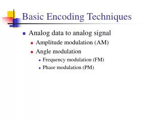
Analog ModulationTechniques • Amplitude Modulation (AM) • Frequency Modulation (FM) • Phase Modulation (PM). • AM is the simplest form of modulation • both FM and PM require greater bandwidth than AM.
Digital Data, Analog Signals Networks and Communication Department
Digital Data, Analog Signal • Some transmission media only transmit analog signals. • Public telephone system • 300Hz to 3400Hz (voice frequency range) • Use modem (modulator-demodulator)
Digital to Analog modulation techniques: Modulation involves operation on signal characteristics: frequency, phase, amplitude. • Amplitude shift keying (ASK) • Frequency shift keying (FSK) • Phase shift keying (PSK)
Amplitude Shift Keying • encode 0/1 by different carrier amplitudes • usually have one amplitude zero • susceptible to sudden gain changes • inefficient • used for • up to 1200bps on voice grade lines • very high speeds over optical fiber
Binary Frequency Shift Keying • most common is binary FSK (BFSK) • two binary values represented by two different frequencies (near carrier) • less susceptible to error than ASK • used for • up to 1200bps on voice grade lines • high frequency radio • higher frequency on LANs that use coaxial cable.
Multiple FSK • More than two frequencies used • More bandwidth efficient • More prone to error • Each signalling element represents more than one bit
Phase Shift Keying • In PSK, the phase of carrier signal is shifted to represent data • 1- Binary phase shift keying: The simplest scheme uses two phases to represent the two binary digits. • 2- Differential PSK(DPSK). • phase shifted relative to previous transmission rather than some constant reference signal • A binary 0 is represented by sending a signal burst of the same phase as the previous signal burst sent. • A binary 1 is represented by sending a signal burst of opposite phase to the preceding one.
Multilevel PSK • More efficient use of bandwidth • Each signal element represents more than one bit • QPSK: quadrature PSK • shifts of /2 (90o), i.e. 4 different phases • Each signal element represents 2 bits • Multilevel PSK • Can use 8 or more phase angles, and each phase can have more than one amplitude. • The use of multiple levels can be extended to use more phase angles & more than one amplitude • Ex. 9600bps modem uses 12 phase angles, four of which have two amplitudes, in total 16 different signal elements
QPSK (+1,+1) 11 (-1,+1) 01 135 45 -135 -45 (+1,-1) 10 (-1,-1) 00 Networks and Communication Department
Performance of Digital to Analog Modulation Schemes • bandwidth • ASK/PSK bandwidth directly relates to bit rate • multilevel PSK gives significant improvements • in presence of noise: • bit error rate of PSK and QPSK are about 3dB superior to ASK and FSK
Analog Data, Digital Signals Networks and Communication Department
(III) Analog Data, Digital Signal • Digitization • Conversion of analog data into digital data • Digital data can then be transmitted using NRZ-L • Digital data can then be transmitted using code other than NRZ-L • Digital data can then be converted to analog signal • Analog to digital conversion done using a codec (coder-decoder) • Two principle codec techniques • Pulse Code Modulation • Delta modulation
Pulse Code Modulation • Sampling Theorem: If a signal is sampled at regular intervals of time and at a rate higher than twice the highest signal frequency, then the samples contain all the information of the original signal. • For example, voice data are limited to below 4000Hz • 8000 samples per second is sufficient to characterize the voice signal. • Samples are analog samples, called Pulse Amplitude Modulation(PAM) samples. • To convert to digital, each analog sample must be assigned a binary code.
Pulse Code Modulation • Each sample is quantized into some level • The original signal is now only approximated and cannot be recovered exactly • This effect is called quantizing error or quantizing noise • For example, 8 bit sample gives 256 levels • 8000 samples per second and 8 bits per sample gives 64kbps, for a single voice signal.
Non-Linear Coding • The PCM scheme is refined using a technique known as nonlinear encoding, • nonlinear encoding means that the quantization levels are not equally spaced. • Using a greater number of quantizing steps for signals of low amplitude, and a smaller number of quantizing steps for signals of large amplitude. • Reduces overall signal distortion • Nonlinear encoding can significantly improve the PCM SNR ratio. • For voice signals, improvements of 24 to 30 dB have been achieved
Companding • The same effect can be achieved by using uniform quantizing but companding (compressing-expanding) the input analog signal. • Companding is a process that compresses the intensity range of a signal by set more gain to weak signals than to strong signals on input. • At output, the reverse operation is performed.
Delta Modulation • Analog input is approximated by a staircase function • can move up or down one level () at each sample interval • has binary behavior • since function only moves up or down at each sample interval. • hence can encode each sample as single bit. • 1 for up or 0 for down
PCM verses Delta Modulation • DM has simplicity compared to PCM • but has worse SNR • issue of bandwidth used • e.g. for good voice reproduction with PCM • want 128 levels (7 bit) & voice bandwidth 4khz • need 8000 x 7 = 56kbps • data compressioncan improve on this • still growing demand for digital signals • use of repeaters, TDM, efficient switching • PCM preferred to DM for analog signals
Problem • Q5. The analog waveform shown in the following figure is to be delta modulated. The sampling period and the step size are indicated by the grid. The first DM output is also shown. Give the DM output for the complete signal.
Reference • Data and Computer Communications, Ninth Edition by William Stallings, • Chapter 5 (5.2 , 5.3, 5.4) Networks and Communication Department