Download

1 / 84
840 likes | 1.09k Vues
#9: Scan Conversion & Midterm Review. CSE167: Computer Graphics Instructor: Ronen Barzel UCSD, Winter 2006. Outline for Today. Rendering intro Culling & clipping Scan conversion Midterm review. Rendering. Fancier term: Image Synthesis

E N D
#9: Scan Conversion & Midterm Review CSE167: Computer Graphics Instructor: Ronen Barzel UCSD, Winter 2006
Outline for Today • Rendering intro • Culling & clipping • Scan conversion • Midterm review
Rendering • Fancier term: Image Synthesis • Synthesis of a 2D image from a 3D scene description • Result is a 2D array of pixels • Red, Green, Blue values (range 0-255 or 0.0-1.0) • Can also have: opacity (“alpha”), depth (“Z”), … • Rasterization = determining which pixels are drawn by a given object
Hardware vs. Software Rendering • Highest quality rendering is done by software • Algorithms such as “ray tracing”, “photon maps”, etc… • Fanciest lighting, shadowing, surface shading, smoke & fog, etc. • Can take minutes or hours to compute an image • RenderMan (Pixar), Dali (Henrik Wann Jensen), RADIANCE, POVRay, … • Modern computers often have special-purpose 3D rendering hardware. • “GPU” == Graphics Processing Unit. (Nvidia, ATI) • Hardware implements the traditional 3D graphics rendering pipeline • Very fast, but relatively simple algorithm: • Limits ability to get subtle shadows, reflections, etc. • Limits on complexity of surface shading description, etc. • Continually improving, driven by games industry. • (Modern graphics hardware is programmable, blurring the distinction between hardware & software rendering.) • We will start with algorithms that are used by GPUs, but we’ll do them in software.
3-D Graphics Rendering Pipeline Primitives Object space Modeling Transformation World space Viewing Transformation Camera space (I added this stepto the diagram) Culling Lighting & Shading Clipping Projection Today Normalized view space Scan conversion, Hiding Image space, Device coordinates Image
Rendering Triangle Sets • Will focus on triangles for now • Most basic and useful • Algorithms also for lines, points, polygons, circles, ellipses, … • Assume we have colors • I.e., colors assigned per-vertex • Next week we’ll look at lighting
We’ve already done culling • Assume we’ve already culled to the view volume: • We’ve tossed out objects that we know are outside the view • Does that mean everything that remains will be drawn…?
More culling, and clipping • The view volume culling may have been coarse per-triangle view volume culling • Some triangles may intersect the edge of the view volume clipping • Some triangles may be on the back sides of objects backface culling • Some triangles may be obscured by other triangles hidden surface elimination , AKAhiding • Some triangles may be degenerate degenerate culling • We will do culling/clipping before we rasterize triangles • We will do hidden-surface elimination at the last step
Outline for Today • Rendering intro • Culling & clipping • Scan conversion • Midterm review
Culling • The sooner we can detect that a triangle is not going to be visible, the less time has to be spent processing it • We did object-level frustum culling. • Now we cull individual triangles • There are three common reasons to cull a triangle: • If it doesn’t lie within the view volume (view frustum culling) • If it is facing ‘away’ from the viewer (backface culling) • If it is degenerate (area=0) • We’ll get to the first case later, when we do clipping
Backface Culling • Commonly use triangles to model the surface of a solid object • If the object has no holes, the triangles will only be seen from the outside. • Consider the triangles as “one-sided”, i.e. only visible from the ‘front’ • If the ‘back’ of the triangle is facing the camera, it can be culled • Back facing triangles should be culled as early as possible • Expect roughly 50% of triangles in a scene to be back facing. • Usually, backface culling is done before clipping: • a very quick operation • affects a much larger percentage of triangles than clipping
p2 p0 p1 Backface Culling • By convention, the front is the side where the vertices are ordered counterclockwise: • Why not backface cull based on specified normals? • Normals not always specified • Per-vertex normals might not agree • Not used in same section of hardware: • normal vector used for lighting/shading only, • not necessarily available to clipping/culling/rasterizing units • Most renderers allow triangles to be defined as one- or two-sided. • Two-sided triangles not backface culled • Used for thin objects, non-closed objects • Many renderers also allow: • specifying whether vertices are ordered clockwise or counterclockwise • specifying whether to cull front or back faces • instead of culling, draw in a different color
Backface Culling • Can cull in any convenient space • Usually backface cull in camera space • Can also backface cull in object space • transform camera position into object coords • don’t have to transform triangles at all before culling
Degenerate Culling • A degenerate triangle has no area, nothing to draw • Can happen happen if all 3 vertices lie in a straight line • Can happen if 2 or all 3 vertices are located at the exact same place • The backface cull test will automatically reject these, as the normal will be zero:
Clipping • For triangles that intersect the faces of the view volume • Partly on screen, partly off • Don’t want to rasterize the parts that are offscreen • Cut away the parts outside the view volume. • Algorithm works on one triangle at a time • Fancier algorithms could work on strips or meshes, and share some work
Clipping planes • The view volume is defined by 6 planes • Orthographic, perspective, or normalized view cube • Each plane defines an inside and an outside • A single triangle might intersect any of them • Geometrically possible to intersect all 6 at once! • More common to intersect at most one or two • Turns out not to make a difference for the algorithm… Inside Outside
Clipping Algorithm • Algorithm: test triangle against each plane • If triangle intersects the plane, clip it so it lies entirely inside: • May become one new triangle • May become two new triangles • These are then tested against the remaining clipping planes • After every plane has been tested, resulting triangle(s) are inside Inside Outside
Clipping to a plane • Determine which of the triangle’s 3 vertices are on which side of the plane • If all 3 vertices are on the ‘inside’, then the triangle doesn’t need to be clipped • If all 3 vertices are on the ‘outside’, then the triangle is completely off-screen • Throw it away • This is per-triangle culling -- comes for free when clipping • If 1 vertex is inside, then clip: create two vertices on the plane, and a single new triangle • If 2 vertices are inside, clip: create two vertices on the plane, and two new triangles clip cull clip Inside Outside
Remember: Signed Distance to Plane • Plane represented by normal and distance d from origin • The distance has a sign: • positive on the side of the plane the normal points to • negative on the opposite side • (0 exactly on the plane) • x Positive Negative
Remember: view volume with oriented planes • Normal of each planepoints outside • “outside” means positivedistance • “inside” means negativedistance
Vertex Inside/Outside Testing • Similar to frustum culling • Compute signed distance to plane for each of the three vertices, v0, v1, and v2 • Negative (or 0): vertex is inside the view volume • Positive: vertex is outside the view volume d0 v0 v1 d1 v2 d2 v1 d0 v0 d1 v2 d2 Inside Outside
Triangle clipping • For triangle that intersects a clipping plane • Determine which two edges intersect plane • Exactly two edges will have opposite sign for each vertex d0 v0 v1 d1 v2 d2 v1 d0 v0 d1 v2 d2 Inside Outside
Triangle clipping • For triangle that intersects a clipping plane: • Determine which two edges intersect plane • Compute intersection of each of those two edges with plane • (we’ll see how in a moment) Inside Outside
Triangle clipping • For triangle that intersects a clipping plane: • Determine which two edges intersect plane • Compute intersection of each of those two edges with plane • Construct new triangle or triangles. Inside Outside
Edge-Plane Intersection • Given triangle edge with va and vb on opposite sides of the plane,having signed distances da and db • Compute point x where the edge intersects the plane: db vb x va da
Clipping: Spaces • Clipping can be done in any convenient space • Can clip in camera space • Ordinary 3D space • Clipping planes are conveniently described in this space • But must transform vertices to camera space, clip, then transform rest of the way • Can clip in normalized view space • Clipping planes are very convenient (faces of normalized cube) • But have already performed divide-by-w (expensive) • If careful, can clip after applying perspective matrix, but before divide-by-w.
Outline for Today • Rendering intro • Culling & clipping • Scan conversion • Midterm review
Where are we now? • Assume: • We are rendering triangles with per-vertex colors • We’ve transformed to image space/device coordinates • x,y are actual pixel coordinates • z is -1 to 1 pseudo-distance (but we don’t care about z for now) • We’ve culled and clipped so that every triangle lies entirely on screen
Rendering • Determine: • Which pixels covered by each triangle (Rasterization) • What color at that pixel • Which triangle is frontmost, in case of overlap
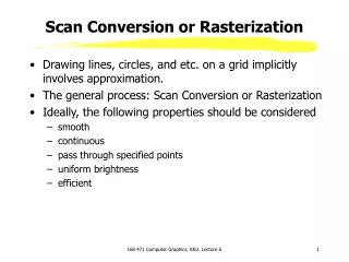
Various algorithms: • Surface subdivision • Spatial subdivision • Edge equations • Scan Conversion
Scan Conversion • We have 2D triangles in device coordinates • Draw each 2D triangle on the screen (or in the image) • Fill in the pixels that are covered by the triangle • For now, just find the right pixels • Later on, interpolate per-vertex data such as depth, color, normal, or other info • Operate scanline by scanline (row-by-row) in the image • On each scanline, find the region that the triangle occupies • Fill those pixels. • Lots of variations of scan conversion algorithms. • We’ll look at the fundamental idea
4.0, 3.0 . 0.0, 0.0 2.5, 0.5 Device coordinates • Viewport with 800 x 600 pixels device coordinates range from 0.0 to 800.0 in x and 0.0 to 600.0 in y • The centers of pixels are on the 1/2’s: • The center of the lower left pixel is 0.5, 0.5 • The center of the upper right pixel is 799.5, 599.5 • The first row of pixels is at y=0.5 • The first column of pixels is at x=0.5
Rasterization Rules • Rules: • Fill a pixel if the center of the pixel lies within the triangle • If a pixel center exactly touches the edge or vertex of the triangle: • Fill the pixel only if the triangle extends to the right(extends mathematically even an infinitesmal amount less than a pixel) • Need precise rules like this to ensure: • that pixels are rendered the same way regardless of order triangles are rendered • that if two triangles share an edge, no pixels are left out along the border • that if two triangles share an edge, no pixels are drawn twice on the border • Important: vertex coordinates in device space are floating point values • should not be rounded to integers
Triangle Scan Conversion • Start at the top of the triangle • Work our way down one scanline at a time • For each scanline, we will fill from left to right • This is the most common way people think of it, but • Different renderers may do it in which ever order they want • In a hardware renderer, the order might be arranged in such a way as to optimize memory access performance
Triangle Scan Conversion • Input: three 2D vertices • possibly with depth, color, normal, data per vertex • Sort the vertices into top-down order, label them: • v0 is now the top (highest y value), • v1 in the middle, • v2 at the bottom • This may break our counterclockwise ordering • don’t care: we’re past backface culling • don’t care: doesn’t affect per-vertex normal data • Steps: • Fill the top half of the triangle: between v0 and v1 • Fill the bottom half of the triangle: between v1 and v2 • Notes: • if v0 and v1 have same y value, no top half • if v1 and v2 have same y value, no bottom half • v0 and v1 and v2 have same y value? degenerate, already culled
Slope Computation • Compute the slope of each edge: • How much the x-value changes with each full pixel step in y dyL dyR dxR dxL
Find The First Scanline • To start filling the top half of the triangle (from v0 to v1): • determine the first scanline to start on, i.e. the 1/2-pixel y coordinate • determine the x values where edges v0v1 and v0v2 intersect that scanline • We can use the computed slopes to do this quickly
Filling The Span • Now fill pixels whose centers lie between xL and xR
Looping in Y • Loop through all scanlines from v0 down to v1 • At each scanline, update x0 and x1 incrementally with the slopes
Looping in Y • We loop from v0 down to v1 • Then recompute the slope of the v1 edge • Filling bottom half from v1 down to v2 proceeds same as the top half
Scan Conversion • There is some cost in the set-up: • calculate slopes, initial y and x values • several divisions, etc. • The cost per scanline and per pixel is very low • take advantage of incremental computation • In hardware, scan conversion is usually done with fixed point math • much of the work can be done with low precision fixed point • 16 bits is usually fine for most operations
Interpolating color • For solid-color triangles, fill each pixel with the color • With per-vertex colors, want to interpolate color smoothly across the triangle • known Gouraud Interpolation or Gouraud Shading
Bilinear Color interpolation • Given RGB values at each vertex: v0r, v0g, v0b etc. • Same structure, but with interpolation along each scanline as well as from one scanline to the next:
Interpolating other data • For lighting calculations, can interpolate per-vertex normals to each pixel (next week) • For texture mapping, can interpolate per-vertex texture coordinates to each pixel (in a few weeks) • Use same structure as for color interpolation
Hidden Surface Removal • Don’t draw pixels of triangles that are blocked by others • Intuitive approach: pre-sort triangles, and draw them back-to-front • Closer triangles overwrite farther triangles • Known as Painter’s Algorithm • Problem: slow to sort all the triangles • Problem: triangles don’t always have a well-defined order
Z-Buffer, AKA Depth Buffer • At each pixel, store a depth (z) value along with the RGB color • Before starting to render a frame, set all z values to the furthest possible value • When rasterizing, compute the z value at each pixel • Compare computed z value to the value stored in the buffer • If computed z value is farther than stored value, leave pixel as is • If computed z value is nearer than stored value, fill pixel and store new z value • How to compute z value at each pixel…? • We chose projection to preserve straight lines: also preserves flatness of triangles • So we can linearly interpolate z from per-vertex z values. • Like color interpolation, this is bi-linear • dz/dy and dz/dx are constant on the triangle, can compute them once
Z-Buffer • Great, simple, fast technique • Used in all GPU renderers • First used by Ed Catmull in his 1974 PhD thesis • At the time it was an extreme solution: “huge” memory cost • (Since then, Ed Catmull founded Pixar…) • Doesn’t directly handle fancier features such as transparency, shadowing, smoke • Fancier features generally require computing effects that depend on relationships between objects. • Hard to do that when processing each triangle independently.
Z-buffer resolution • Generally have fixed resolution in z, e.g. 32 bits • Perspective mapping causes near objects to have more depth resolution than far things. • Because of limited resolution, can have “z-fighting”: • If two triangles are co-planar to within the z-resolution, it’s arbitrary which one will be chosen at each pixel • If they have different colors, the color will flicker or have strange patterns • To increase effective resolution: • Remember, projection transforms map everything between near & far planes to min,max in depth • The farther apart near & far planes are, the less resolution available to distinguish things between them • Put near & far planes as close together as you can: minimize the raio of far/near distance • near clip distance of 0.1 and far clip distance of 1000 (i.e., ratio of 10,000) generally works OK for 32 bits.