Download
1 / 18
200 likes | 530 Vues
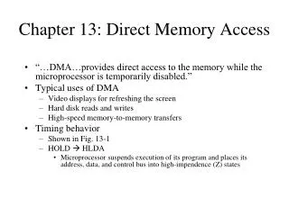
Direct Memory Access. Presentation by Leena Jacob. To be tackled. The basic computer Improvements made to the basic computer Interrupt handler DMA DMA Controller in BF533 Example code that demonstrates setting up the DMA. Steps involved in storing data to the memory by the I/O device:

E N D
Direct Memory Access Presentation by Leena Jacob
To be tackled • The basic computer • Improvements made to the basic computer • Interrupt handler • DMA • DMA Controller in BF533 • Example code that demonstrates setting up the DMA
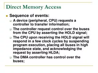
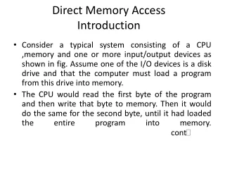
Steps involved in storing data to the memory by the I/O device: CPU signals I/O device I/O places data on the bus and signals to CPU CPU reads the data into a register and signals to I/O CPU signals memory Memory writes data to some location Memory signals CPU that it is done. The basic computer
Deficiencies of CPU I/O • No other useful CPU operations can be accomplished while waiting for I/O • Early I/O devices were very slow, thus compounding the problem
Interrupt Improvements • The better option is for the I/O device to interrupt the processor with an interrupt signal whenever it is ready with a data. • CPU can then service the interrupt and get back to whatever it was doing before. • This requires an interrupt handler.
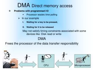
Direct Memory Channel Improvement • Interrupt processing requires explicit op-code cycles to perform I/O transfers • Next improvement is a separate peripheral module to perform direct memory access (DMA). • It is also the bus arbitrator. • There can only be one user of the data bus so processor must wait if DMA is transferring data. • DMA controller tells the processor when the DMA has completed the transfer.
DMA Block Diagram Interrupt line cycle state signals CPU DMA Module External I/O lines address setup Address bus Data bus RAM
Sharing of the op-code cycles • Op-code cycles have two distinct parts: • One part involves RAM access • Read the OP code from program memory (fetch) • Read/write data from/to data RAM addresses (decode and writeback) • Second part involves only CPU operations (execute) • Perform data manipulation using CPU registers as source(s) and destination(s) of data • DMA device performs RAM access during this second portion of the op-code cycle
DMA Controller in BF533 • Between memory and memory (MDMA) (“Memory DMA”) • Between memory and the I/O through a serial or parallel port (SPI, PPI,UART). • There are 12 DMA channels for various transfers. • Two ways of programming DMA transfers • Descriptor-based • Register-based
Descriptor-based DMA • Descriptor-based DMA transfers require a set of parameters stored within memory to initiate a DMA sequence. • This sort of transfer allows the chaining together of multiple DMA sequences. • In descriptor-based DMA operations, a DMA channel can be programmed to automatically set up and start another DMA transfer after the current sequence completes.
Register-based DMA • Register-based DMA allows the processor to directly program DMA control registers to initiate a DMA transfer. • On completion, the control registers may be automatically updated with their original setup values for continuous transfer, if needed.
DMA Registers DMA registers fall into three categories: • Parameter registers, such as DMAx_CONFIG and DMAx_X_COUNT • Current registers, such as DMAx_CURR_ADDR and DMAx_CURR_X_COUNT • Control/Status registers, such as DMAx_IRQ_STATUS and DMAx_PERIPHERAL_MAP
Video Interface DMA VideoInPort Decoder Video source PPI Interface Memory Display Unit PPI Interface VideoOutPort Encoder BF533
Example code for video Input //Configure the Interrupt service routine CALL BF533_EZ_KIT_ISR_Config; //Configure the SDRAM CALL BF533_EZ_KIT_SDRAM_Config; //Configure the DMA in Stop Mode CALL BF533_EZ_KIT_DMA_Config; //Configure the PPI 8bit, ITU-656 mode, Input Mode, Active Field Only...... CALL BF533_EZ_KIT_PPI_Config;
Config_DMA_Input: //Target address of the DMA r0.h = 0x0; r0.l = 0x0; P0.L = lo(DMA0_START_ADDR); P0.H = hi(DMA0_START_ADDR); [P0] = R0; //DMA0_Y_COUNT R0.L = 0x020D; P0.L = lo(DMA0_Y_COUNT); P0.H = hi(DMA0_Y_COUNT); W[P0] = R0.L; //DMA0_Y_MODIFY R0.L = 0x0001; P0.L = lo(DMA0_Y_MODIFY); P0.H = hi(DMA0_Y_MODIFY); W[P0] = R0.L; //PPI Peripheral is used r0 = 0x0000(z); P0.L = lo(DMA0_PERIPHERAL_MAP); P0.H = hi(DMA0_PERIPHERAL_MAP); W[P0] = R0.L; //DMA Config: Enable DMA | Memory write DMA | Discard DMA FIFO before start | enable assertation of interrupt | | Enable STOP DMA P0.L = lo(DMA0_CONFIG); P0.H = hi(DMA0_CONFIG); r0 = DMAEN | WNR | RESTART | DI_EN(z); W[P0] = R0.L; Example code that sets-up DMA
Interrupt service routine //clear DMA interrupt P0.L = lo(DMA0_IRQ_STATUS); P0.H = hi(DMA0_IRQ_STATUS); R0.L = W[P0]; BITSET(R0,0); W[P0] = R0.L;
Tackled today • The basic computer • Improvements made to the basic computer • Interrupt handler • DMA • DMA Controller in BF533 • Example code that demonstrates setting up the DMA • Importance of DMA transfers in DSP algorithms
References • http://engr.smu.edu/~levine/ee8304/4 • Analog Device’s BF533 hardware manual • http://www.technology.niagarac.on.ca/courses/comp530/DMANotes.htm