Download
1 / 18
180 likes | 357 Vues
Internetworking connectionless and connection-oriented networks. Malathi Veeraraghavan Mark Karol Polytechnic University Bell Labs. mv@poly.edu mk@lucent.com Outline: Why internetwork? Prior work Our proposal. Connectionless (CL) Network. CL Network. Connection-Oriented (CO)

E N D
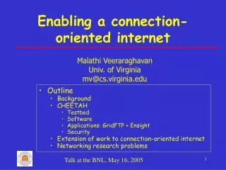
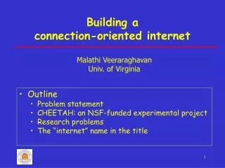
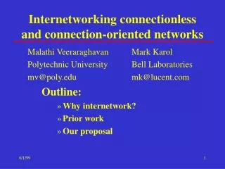
Internetworking connectionless and connection-oriented networks Malathi Veeraraghavan Mark Karol Polytechnic University Bell Labs. mv@poly.edu mk@lucent.com Outline: • Why internetwork? • Prior work • Our proposal
Connectionless (CL) Network CL Network Connection-Oriented (CO) Network Case 3 Router Endpoint Switch Endpoint Case 2 Case 1 Why internetwork?
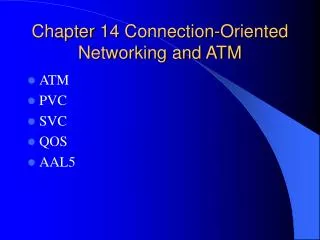
Networking modes Connection-oriented Connectionless Switching modes ATM Packet-switching IP Telephony network, SONET/SDH, WDM Circuit-switching Problem Statement • Applications at endpoints start sending data without warning in connectionless networks • CO networks need a connection setup phase • So how do the gateways cope with the traffic arriving from the CL networks without time to set up a connection?
Use provisioned connections • Use provisioned connections through CO network • Suitable for some cases CL Network CL Network CO Network Case 1 Provisioned connections: set up a priori based on anticipated traffic Switched connections: set up on demand as traffic arrives
Switched connections • Need switched connections for some cases • CL applications have an application-level handshake that can be used to trigger connection setups • e.g., interconnecting an Internet telephony PC to a telephone • e.g., H.245 signaling to Q.931 signaling through the PSTN phone CL Network Router Endpoint Gateway Switch CO Network Endpoint Case 2
Prior work • Interesting case - Case 3 • A choice exists of which network to use • Existing solutions: • MPOA (Multi-Protocol Over ATM) • MPLS (Multi-Protocol Label Switching) CL Network CO Network Case 3
IP packet 7 10 5 1 1 1 1 SETUP Solutions - MPOA • MPOA: • Overlay model • Routing data not shared • Good solution if choice to use CO network made based on application needs (e.g., interactive sessions with long holding times) CL Network Interactive application (long-lived flow; if flow classifier is set to use CO network for this flow type) CO Network
IP packet 7 10 5 1 1 1 6 1 IP packet 1 IP packet 1 1 Solutions - MPOA • MPOA: • Not a good solution if either CL or CO network can be used for a given application (e.g., large bulk-data transfers) CL Network Does not take advantage of shorter path through the CO network CO Network Large bulk-data transfers can be handled by either network - if flow classification does not detect this as a flow to be handled by the CO network
IP packet 7 10 5 1 1 1 6 IP packet IP packet 1 1 SETUP SETUP 1 1 IP packet IP packet SETUP SETUP Solutions - MPLS • MPLS: • Peer model • Routing data is shared • Requires every CO switch to also be a CL router • Consider same example as last slide - large bulk-data transfer that could go either way CL Network Gateway will select CO network because path is shorter CO/CL Network Packets will be forwarded in CL mode while connection is being set up
Proposed solution • Peer model • Routing data is shared • How is this done: routing-related actions • But, not all nodes in the CO network need to have CL capability • Problem created: • Data arrives from the CL endpoints into the gateway before connections are set up • User-plane actions
GW1 GW2 GW3 Note: switches have no CL capability Routing related actions • Gateways running OSPF connected by a CO network (non-broadcast network) announce point-to-point links between gateways S4 S2 R6 R3 R1 S1 S5 R5 R2 R7 S3 R4 CO Network CL Network
2 1 5 1 1 1 2 3 1 1 1 1 2 4 1 Routing related actions • Topological view of each router and gateway GW1 R6 R3 Shortest path from R4 to R7 is via GW3 and GW2 GW2 R1 R5 R2 R7 GW3 R4 CL Network User data packets from R4 to R7 arrive at GW3 even before connection is set up
User-plane actions • IP datagrams arrive at the gateway to be carried through the CO network when no connection exists through it. • IP datagram could be carrying a TCP segment • IP datagram could be carrying a UDP datagram • CO network used only for flows classified as needing connections or those that can be handled on either network
For flows for which the CO network is to be used • TCP segment • If it is a SYN segment, hold it up, set up connection • SYN-related time-outs are large (5 sec) • If it is a data segment, then send zero-window acknowledgment to halt data • if persist timers get routed through some other path and data arrives before connection is set up, send another zero-window ack.
For flows for which the CO network is to be used • UDP datagram • For applications with user-level message exchange, hold up such messages and set up connection (e.g., H.245 open logical channel) • For applications without such exchanges • use source routing to override default routes • use small-bandwidth provisioned pipes
Streaming e.g., live or stored audio or video Interactive e.g., telnet, rlogin, telephony Bulk-data e.g. ftp, smtp, http Small amounts of data transfer Large amounts of data transfer Applications Circuit-switched (CO) networks Packet-switched CO networks CL (packet-switched) networks Circuit-switched or CL networks Peer model needed for this case
Protocol conversion vs. protocol encapsulation • ATM or label overhead incurred on connection with protocol encapsulation (+ TCP ACKs overhead) • This can be avoided with protocol conversion • Much simpler transport-layer protocol can be used in CO network since the network nodes now maintain state and congestion control (instead of state information being maintained at endpoints) • Can use protocol conversion in switched mode • Drawback: TCP state information about many connections needs to be held at the gateways • Feasibility as yet untested.
Conclusions • For applications whose data can be carried in either the CL network or CO network, internetworking should allow for the exchange of routing information (peer model) • Requiring all CO nodes to have CL capability seems too constraining (an MPLS requirement) • Hence, our proposed solution: • Share routing data • “Halt” or “turn back traffic” while setting up connections