Download
1 / 24
240 likes | 265 Vues
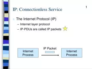
Network Layer Connection vs. Connectionless Service. datagram network provides network-layer connectionless service VC network provides network-layer connection service analogous to the transport-layer services, but: service: host-to-host

E N D
Network Layer Connection vs. Connectionless Service • datagram network provides network-layer connectionless service • VC network provides network-layer connection service • analogous to the transport-layer services, but: • service: host-to-host • generally no choice: network typically provides one or the other • implementation: in network core • network vs transport layer connection service: • network: between two hosts, in case of VCs, also involves intervening routers • transport: between two processes CSci4211: Network Layer: Data Plane Part 1
Objective of both: move packets through routers from source to destination Datagram Model: Routing: determine next hop to each destination a priori Forwarding: destination address in packet header, used at each hop to look up for next hop routes may change during “session” analogy: driving, asking directions at every gas station, or based on the road signs at every turn Virtual Circuit Model: Routing: determine a path from source to each destination “Call” Set-up: fixed path (“virtual circuit”) set up at “call” setup time, remains fixed thru “call” Data Forwarding: each packet carries “tag” or “label” (virtual circuit id, VCI), which determines next hop routers maintain”per-call” state Virtual Circuit vs. Datagram CSci4211: Network Layer: Data Plane Part 1
call setup/teardown for each call before data can flow need special control protocol: “signaling” every router on source-dest path maintains “state” (VCI translation table) for each passing call VCI translation table at routers along the path of a call “weaving together” a “logical connection” for the call link, router resources (bandwidth, buffers) may be reserved and allocated to each VC to get “circuit-like” performance Compare w/ transport-layer “connection”: only involves two end systems, no fixed path, can’t reserve bandwidth! “source-to-dest path behaves much like telephone circuit” (but actually over packet network) performance-wise network actions along source-to-dest path Virtual Circuits CSci4211: Data Link Layer
VC Implementation a VC consists of: • path from source to destination • VC numbers, one number for each link along path • entries in forwarding tables in routers along path • packet belonging to VC carries VC number (rather than dest address) • VC number can be changed on each link. • New VC number comes from forwarding table CSci4211: Data Link Layer
used to setup, maintain teardown VC used in ATM, frame-relay, X.25; MPLS used in part of today’s Internet: Multi-Protocol Label Switching (MPLS) operated at “layer 2+1/2” (between data link layer and network layer) for “traffic engineering” purpose application transport network data link physical application transport network data link physical 6. Receive data 5. Data flow begins 4. Call connected 3. Accept call 1. Initiate call 2. incoming call Virtual Circuit: Signaling Protocols CSci4211: Data Link Layer
Virtual Circuit Setup/Teardown Call Set-Up: • Source: select a path from source to destination • Use routing table (which provides a “map of network”) • Source: send VC setup request control (“signaling”) packet • Specify path for the call, and also the (initial) output VCI • perhaps also resources to be reserved, if supported • Each router along the path: • Determine output port and choose a (local) output VCI for the call • need to ensure that no two distinct VCs leaving the same output port have the same VCI! • Update VCI translation table (“forwarding table”) • add an entry, establishing an mapping between incoming VCI & port no. and outgoing VCI & port no. for the call Call Tear-Down: similar, but remove entry instead CSci4211: Data Link Layer
VC number 22 32 12 3 1 2 interface number Incoming interface Incoming VC # Outgoing interface Outgoing VC # 1 12 3 22 2 63 1 18 3 7 2 17 1 97 3 87 … … … … VC Translation/Forwarding Table Forwarding table in northwest router: Routers maintain connection state information! CSci4211: Data Link Layer
1 1 green call four “calls” going thru the router, each entry corresponding one call purple call blue call orange call VCI translation table (aka “forwarding table”), built at call set-up phase 2 3 2 2 1 1 During data packet forwarding phase, input VCI is used to look up the table, and is “swapped” w/ output VCI (VCI translation, or “label swapping”) CSci4211: Data Link Layer
Virtual Circuit: Example “call” from host A to host B along path: host A router 1 router 2 router 3 host B • each router along path maintains an entry for the call in its VCI translation table • the entries piece together a “logical connection” for the call • Exercise: write down the VCI translation table entry for the call at each router Router 4 0 Router 1 3 1 2 Router 2 2 3 1 5 11 0 Host A 7 Router 3 0 1 3 4 Host B 2 CSci4211: Data Link Layer
ATM and MPLS • ATM, MPLS separate networks in their own right • different service models, addressing, routing from Internet • viewed by Internet as logical link connecting IP routers • just like dialup link is really part of separate network (telephone network) • ATM, MPSL: of technical interest in their own right CSci4211: Data Link Layer
Asynchronous Transfer Mode: ATM • 1990’s/00 standard for high-speed (155Mbps to 622 Mbps and higher) Broadband Integrated Service Digital Network architecture • Goal:integrated, end-end transport of carry voice, video, data • meeting timing/QoS requirements of voice, video (versus Internet best-effort model) • “next generation” telephony: technical roots in telephone world • packet-switching (fixed length packets, called “cells”) using virtual circuits CSci4211: Data Link Layer
ATM Architecture • adaptation layer: only at edge of ATM network • data segmentation/reassembly • roughly analagous to Internet transport layer • ATM layer:“network” layer • cell switching, routing • physical layer CSci4211: Data Link Layer
ATM: Network or Link layer? IP network Vision: end-to-end transport: “ATM from desktop to desktop” • ATM is a network technology Reality: used to connect IP backbone routers • “IP over ATM” • ATM as switched link layer, connecting IP routers ATM network CSci4211: Data Link Layer
PPP or Ethernet header IP header remainder of link-layer frame MPLS header label Exp TTL S 8 1 3 20 Multiprotocol Label Switching (MPLS) • initial goal: speed up IP forwarding by using fixed length label (instead of IP address) to do forwarding • borrowing ideas from Virtual Circuit (VC) approach • but IP datagram still keeps IP address! CSci4211: Data Link Layer
MPLS Capable Routers • a.k.a. label-switched router • forward packets to outgoing interface based only on label value (don’t inspect IP address) • MPLS forwarding table distinct from IP forwarding tables • flexibility: MPLS forwarding decisions can differ from those of IP • use destination and source addresses to route flows to same destination differently (traffic engineering) • re-route flows quickly if link fails: pre-computed backup paths (useful for VoIP) CSci4211: Data Link Layer
MPLS versus IP paths R6 D R4 R3 R5 A R2 • IP routing: path to destination determined by destination address alone IP router CSci4211: Data Link Layer
MPLS versus IP paths entry router (R4) can use different MPLS routes to A based, e.g., on source address R6 D R4 R3 R5 A R2 • IP routing: path to destination determined by destination address alone IP-only router • MPLS routing: path to destination can be based on source and destination address • fast reroute: precompute backup routes in case of link failure MPLS and IP router CSci4211: Data Link Layer
MPLS Signaling • modify OSPF, IS-IS link-state flooding protocols to carry info used by MPLS routing, • e.g., link bandwidth, amount of “reserved” link bandwidth • entry MPLS router uses RSVP-TE signaling protocol to set up MPLS forwarding at downstream routers RSVP-TE R6 D R4 R5 modified link state flooding A CSci4211: Data Link Layer
in out out label label dest interface 10 6 A 1 12 9 D 0 in out out label label dest interface 10 A 0 12 D 0 8 A 1 R6 0 0 D 1 1 R3 R4 R5 0 0 A in out out label label dest interface in out out label label dest interface R2 R1 6 - A 0 8 6 A 0 MPLS Forwarding Tables CSci4211: Data Link Layer
VLANs: motivation consider: • CS user moves office to EE, but wants connect to CS switch? • single broadcast domain: • all layer-2 broadcast traffic (ARP, DHCP, unknown location of destination MAC address) must cross entire LAN • security/privacy, efficiency issues Computer Science Computer Engineering Electrical Engineering CSci4211: Data Link Layer
7 1 2 8 15 9 10 16 VLANs Virtual Local Area Network 15 7 9 1 2 8 10 16 port-based VLAN: switch ports grouped (by switch management software) so that singlephysical switch …… switch(es) supporting VLAN capabilities can be configured to define multiple virtualLANS over single physical LAN infrastructure. … … Computer Science (VLAN ports 9-15) Electrical Engineering (VLAN ports 1-8) … operates as multiple virtual switches … … Computer Science (VLAN ports 9-16) Electrical Engineering (VLAN ports 1-8) CSci4211: Data Link Layer
forwarding between VLANS: done via routing (just as with separate switches) • in practice vendors sell combined switches plus routers Port-based VLAN router • traffic isolation:frames to/from ports 1-8 can only reach ports 1-8 • can also define VLAN based on MAC addresses of endpoints, rather than switch port 15 7 9 1 2 8 10 16 • dynamic membership: ports can be dynamically assigned among VLANs … … Computer Science (VLAN ports 9-15) Electrical Engineering (VLAN ports 1-8) CSci4211: Data Link Layer
1 16 VLANs Spanning Multiple Switches 15 7 9 7 1 3 5 • trunk port:carries frames between VLANS defined over multiple physical switches • frames forwarded within VLAN between switches can’t be vanilla 802.1 frames (must carry VLAN ID info) • 802.1q protocol adds/removed additional header fields for frames forwarded between trunk ports 2 8 10 4 6 2 8 … … Computer Science (VLAN ports 9-15) Ports 2,3,5 belong to EE VLAN Ports 4,6,7,8 belong to CS VLAN Electrical Engineering (VLAN ports 1-8) CSci4211: Data Link Layer
802.1Q VLAN frame format type source address dest. address preamble data (payload) 802.1 frame CRC type 802.1Q frame data (payload) CRC 2-byte Tag Protocol Identifier (value: 81-00) Recomputed CRC Tag Control Information (12 bit VLAN ID field, 3 bit priority field like IP TOS) source address dest. address preamble CSci4211: Data Link Layer