Download
1 / 9
90 likes | 220 Vues
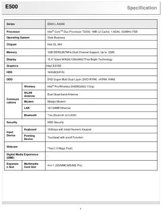
Digital specification. Keep signal treatment ( dynamic pedestal subtraction) Keep present trigger construction Save space => 8 channels/FPGA Decrease Fiber number by data compression in FE cards FPGA

E N D
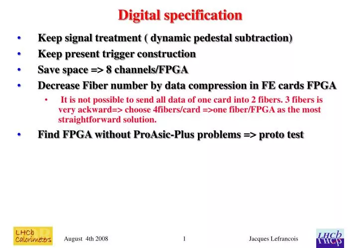
Digital specification • Keep signal treatment ( dynamic pedestal subtraction) • Keep present trigger construction • Save space => 8 channels/FPGA • Decrease Fiber number by data compression in FE cards FPGA • It is not possible to send all data of one card into 2 fibers. 3 fibers is very ackward=> choose 4fibers/card =>one fiber/FPGA as the most straightforward solution. • Find FPGA without ProAsic-Plus problems => proto test Jacques Lefrancois
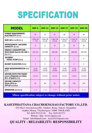
Format of output for 8 ADCs • The data format every 25ns is from 8bytes to 16 bytes long • Code on short or long data for each ADC (If ADC output between pedestal-8 and pedestal+ 23 => code ADC on 5 bits. • Presently in TELL1 we use 4bits to code short ADC => at higher luminosity and larger pile-up this does not work. The justification for 5bits is given slide 23,24,25,26 of • http://indico.cern.ch/getFile.py/access?contribId=4&sessionId=1&resId=1&materialId=slides&confId=59892 • If N ADC output smaller or larger than limit => give the full 12 bits i.e. transmit also N X (12-5) = N X 7 but because of byte organisation => N X 8 • 1byte for the map of 8 short or long ADC • 5bytes for the data of 8 short ADC • up to 8 bytes for long ADC Jacques Lefrancois
Format output /Data coding using RAM • One byte is used for the BXID • One byte is used for the seed information (highest Et cluster 2X2 in the card, which is calculated by the TRIGPGA). • Every 25ns the data to be sent is 8 to 16 bytes long • 8bytes in fixed format and 0 to 8 additional bytes for the long ADCs. • The aim is to pack 256 events of 8 to 16 bytes long received in 256X25ns in a fiber which can send 10 bytes every 25ns. • A solution was presented in June using memory manipulation. It was rather easy to understand but required 52 out of 60 blocks of RAM in the A3PE1500 and required that the RAM be operated at 160 MHz Jacques Lefrancois
Multiplexer solution • After discussions with Federico and Richard it seems than another packing implementation is possible. • It requires a massive use of A3PE cells used as multiplexer, demultiplexers. It can run at 40-80 MHz and requires much less memory blocks Jacques Lefrancois
Pushing zeros in the 16 bytes • From the map byte the number and position of long ADC data is known for example: 00010101 • The data has 8 bytes of fixed formats followed by the 8 long ADC's bytes of which in the case above 5 have zero's • In 8 pipeline steps the data can be shifted so that the non zero data are in the first 3 position. This uses <8 byte multiplexer per step => 64 cells +64 registers 8 steps => 1024 cells • The first 8 bytes of fixed format have to wait =>512 registers Jacques Lefrancois
Packing in the FIFO (I) • The Fiber FIFO is 10 bytes wide and has (for example) a depth of 256. It uses 10 dual port RAM (actually 8X512) • Use for the address of the FIFO I,J I=0,255 J=0,9 • Every 25ns the data bytes which are 8 to 16 have to be written in the FIFO • The address where each non zero byte of a data word is written is the last address of the previous word + K the byte location in the current word => I(N+1),J(N+1) = I(N),J(N) + K • but the adder is such that if J=9+1 => J=0 and I=I+1 (like a decimal adder) • This operation can take more than 25 ns but then it has to be done in pipeline fashion Jacques Lefrancois
Packing in FIFO (II) • The data bytes in any of 16 position can be written in any of the 10 Rams (this is the J part of the address) this is done by 16X10 byte multiplexers =>160X8 cells=>1280cells (+registers?) • In some cases two bytes have to be written simultaneously at the same J at two different but successive value of I this is done using for example leading and falling edge. For example the first 8 bytes of a 8-16 bytes data are written on leading edge of clock the last 8 bytes on falling edge. (This means using RAMs at 80 MHz =>no problem) • VHDL simulation to check? Jacques Lefrancois
Use of FIFO • The FIFO can be used as "standard FIFO" • If many short ADCs => FIFO empty => no data sent into GBT • If too many long ADCs FIFO full => truncate events • Advantage :"standard" • Inconvenient: the synchronisation of the different fibers is lost! • Pseudo FIFO: Alternate between two groups (of 10 RAMs) • Always start a new "package of 256 events" at the top of a RAM • Delay the readout of the FIFO (by 64 clock cycles) such that empty location in the RAM are always at the end of the group of 256 events. • The truncation (if there is some) is also always at the end of the group of 256 events => write a trailer 80 bits in fiber giving fiber location +truncation information Jacques Lefrancois
Empty bunches • Every 256 bunches there is always at least 3 empty bunches=> No data is written (not even the short ADCs) this save some space used to decrease probability of overflow and allows to send the trailer. Jacques Lefrancois