Download
1 / 22
220 likes | 304 Vues
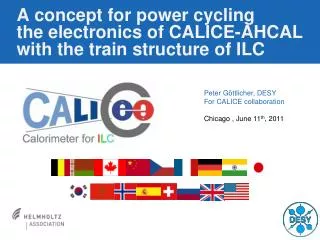
Electronics part of AHCAL calibration system. ECFA meeting at Warszawa. Proposal for calibration system. Fast LED driver is needed for fast photodetectors… A tunable calibration light in the range 0 to 100MIP

E N D
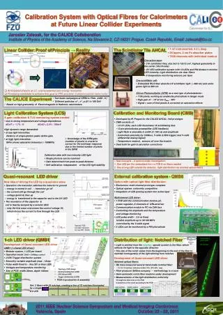
Electronics part of AHCAL calibration system ECFA meeting at Warszawa Ivo Polak, IPASCR, Prague
Proposal for calibration system • Fast LED driver is needed for fast photodetectors… • A tunable calibration light in the range 0 to 100MIP • Simplification of the optical system: one LED -> one side emitting fibre, one row of scintillator tiles • See Jara’s talk Optical part of AHCAL calibrator Ivo Polak, IPASCR, Prague
Two scenarios of calibration system for EUDET AHCAL • Side emitting fiber for one raw, QRLed driver sitting on the side of module (endcap) • QRLed driver is sitting at HBU above the scintillator Ivo Polak, IPASCR, Prague
Side emitting fiber version 24 fibers QR driver + LED 24*3cm² area needed at the main PCB Ivo Polak, IPASCR, Prague
Scenario with QRLed driver by scintillator • One LED, one QRLed driver at HBU • Signals needed: • T-calib • V-calib (single ended) • power +12V QRLed driver will be placed here around This figure is been used by Riccardo Fabbri’s talk Ivo Polak, IPASCR, Prague
Electrical block diagram of the Calibrator LED1 +12V QRLED 1 Power regulator • Optical taps • - notches • drops • # of elements compensate exp attenuation T-calib V-calib LED24 QRLED 24 Ivo Polak, IPASCR, Prague
QR LED driver, basic parameters • Fixed pulse width 2 ÷ 10 ns • LED is an integral part of QR driver • Cosine waveform reduces elmag. x-talk • PCB footprint 2 ÷ 3 cm² • Easy power-pulsing Ivo Polak, IPASCR, Prague
PIN PD response to UVLED LED current 1V => 1A PIN Ivo Polak, IPASCR, Prague
Principal schema of QRLed driver A LED A Ivo Polak, IPASCR, Prague
Toroidal inductors, ~ 30nH All inductors has Non-magnetic core No sensitivity to external mag. field L1 L2 L3 Ivo Polak, IPASCR, Prague
Toroidal inductors - parameters Ivo Polak, IPASCR, Prague
Toroidal inductor soldered Ivo Polak, IPASCR, Prague
Toroidal inductor soldered See thickness of PCB and inductor Ivo Polak, IPASCR, Prague
LED current • Max amplitude 1A Ivo Polak, IPASCR, Prague
LED current zoomed 1A peak 2ns/div Ivo Polak, IPASCR, Prague
Linearity test - preliminary Ivo Polak, IPASCR, Prague
Conclusion • Inductor has been changed from loop to toroidal structure • better magnetic isolation • 2 scenarios for calibration system • QRLed driver at HEB (endcap) fibers needed • QRLed driver in detector on HBU no fibers • At the next HCAL DESY meeting we would like to start the discussion about the integration • It is a part of the EUDET task Multichannel LED calibration prototype Ivo Polak, IPASCR, Prague
Backup slides Ivo Polak, IPASCR, Prague
LED current • View of the LED pulse for a middle amplitude (1.0 A) • Measured with 1GHz voltage differential probe and 1GHz scope TDS4104 at 1Ω smd resistor • 4ns/div 0.5A/div Ivo Polak, IPASCR, Prague
In wider time scale PIN Ivo Polak, IPASCR, Prague
In wider time scale,increase of the amplitude PIN 2mV/div Ivo Polak, IPASCR, Prague